

Definition:- Electromechanical relays that use either electromagnetic attraction or electromagnetic induction principles for their operation. Such relays are called electromagnetic relays.
In other words, all relay works whenever the overcurrent flows in the circuit or whenever there is an abnormality in the system. An electromechanical relay device is used in order to avoid such problems.
Depending on the principle of operation, the electromagnetic relays are of two types, i.e., (i) attracted armature relays, and (ii) induction relays.
(i) Attracted armature relays
Attracted armature relays are the simplest type of relays that works in both alternating current and direct current. The operation of this type of relay is that an armature is attracted to an electromagnet or through a solenoid-covered plunger.
In armature attract relay all use the same principle i.e, electromagnetic attraction for their operation.
The electromagnetic force applied on the armature or a plunger is proportional to the square of the flux in the air gap or we can say the square of its current.
However, in DC relays this force is constant. But in the case of AC relays, the total electromagnetic force moved at double the frequency.
Based on the constructions the attracted armature relays are of the following 6 types:
1. Plunger type
2. Hinged armature type
3. Balanced beam type
4. Polarised moving-iron type
5. Moving-coil type
6. Polarised moving-iron type
7. Reed type
You must also know: Vacuum Circuit Breaker: Construction, Working & Applications
1. Plunger type
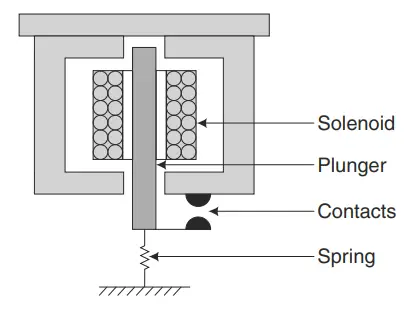
In the plunger-type of the relay, there consists of a solenoid and an iron plunger. The iron plunger will move in and out of the solenoid in order to make and break the contact. This movement of the plunger is controlled by a spring. This type of construction has however become no longer useful because something better has been invented.
2. Hinged Armature-Type Relays
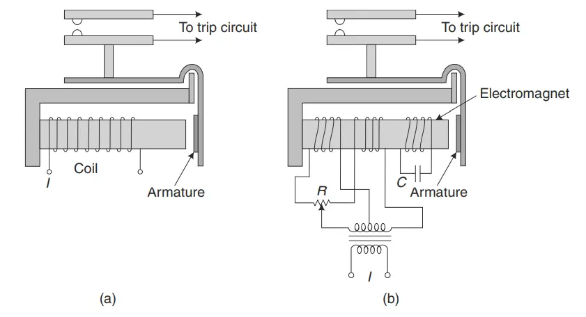
Figure (a) shows a hinged armature-type construction. The operating quantity produces a magnetic flux in the coil which produces an electromagnetic force. Here the electromagnetic force is proportional to the square of the flux in the air gap. It is also proportional to the square of the current. Thus the attractive force increases as the armature approach the pole of the electromagnet. Hinged armature type of relay is mainly used for the protection of small machines, equipment, etc. It is also used for auxiliary relays, such as indicating flags, slave relays, alarm relays, annunciators, semaphores, etc.
The actuating quantity of the relay may be either ac or dc. In dc relay, the electromagnetic force of attraction is constant. In the case of ac relays, sinusoidal current flows through the coil, and hence the force of attraction is given by

From the above expression, it can be understood that the total force is a double frequency pulsating force. So when the frequency is doubled, it may cause the armature to vibrate. Consequently, the relay produces a humming sound and will cause so much noise. This difficulty can be overcome by making the pole of the electromagnet of shaded construction. Alternatively, the electromagnet may be provided with two coils. One coil is energized with the actuating quantity. The other coil gets its supply through a phase-shifting circuit.
The restraining force is provided by a spring. The reset to pick-up ratio for attracted armature type relays is 0.5 to 0.9. For this type of relay, the ratio for ac relays is higher as compared to dc relays. The relay is an instantaneous relay. The operating speed is very high. For a modern relay, the operation time is about 5 ms. It is faster than the induction disc and cup-type relays.
Attracted armature relays are compact, robust, and reliable. They are affected by transients as they are fast and operate on both dc and ac. The fault current contains a dc component at the beginning for a few cycles. Due to the presence of dc transient, the relay may operate though the steady-state value of the fault current may be less than its pick-up. A modified construction as shown in Fig. (b) reduces the effect of dc transients.
3. Balanced Beam Relays
The figure below shows a balanced beam relay which is another type of attracted armature relay. As the name indicates, the relay consists of a beam carrying two electromagnets at its ends. One electromagnet gives operating torque while the other gives retraining torque. The beam is placed at the middle and it remains horizontal under normal conditions.
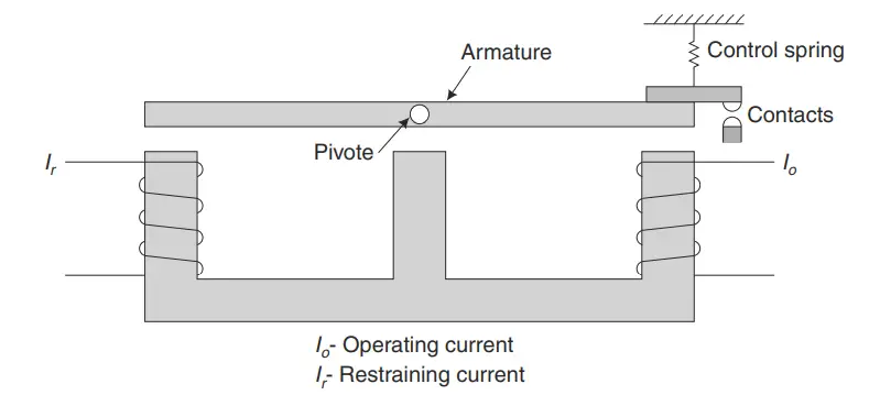
When the operating torque exceeds/crosses the restraining torque, an armature fitted at one end of the beam is pulled and its contacts get disconnected. Though now obsolete, this type of relay was popular in the past for constructing impedance and differential relays. It has been superseded by rectifier bridge comparators and permanent magnet moving coil relays. The beam type relay is robust and fast in operation, usually requiring only 1 cycle, but is not accurate as it is affected by dc transients.
4. Moving Coil Relays
Figure (a) shows a permanent magnet moving coil relay. It is also called a polarised dc moving coil relay. It responds to only dc actuating quantities. It can be used with ac actuating quantities in conjunction with rectifiers. Moving coil relays are the most sensitive type of electromagnetic relays. Modern relays have a sensitivity of 0.1 mW. These relays are costlier than induction cups or moving iron-type relays. The VA burden of moving coil relays is very small. These are used as slave relays with rectifier bridge comparators.
There are two types of moving coil relays: rotary moving coil and axially moving coil type.
The figure above shows a rotary moving coil type construction. The components are a permanent magnet, a coil wound on a non-magnetic former, an iron core, a phosphor bronze spiral spring to provide resetting torque, jeweled bearing, spindle, etc. The moving coil assembly carries an arm that closes the contact. Damping is provided by an aluminum former. The operating time is about 2 cycles. A copper former can be used for heavier damping and slower operation. The operating torque is produced owing to the interaction between the field of the permanent magnet and that of the coil. The operating torque is proportional to the current carried by the coil. The torque exerted by the spring is proportional to deflection. The relay has an inverse operating time/current characteristic.
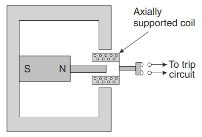
Figure (b) shows an axially moving coil type construction. As this type has only one air gap, it is more sensitive than the rotary moving coil relay. It is faster than the rotary moving coil relay because of light parts. An operating time of the order of 30 msec can be obtained. Sensitivities as low as 0.1 mW can be obtained. Its coils are wound on a cylindrical former which is suspended horizontally. The coil has only axial movement. The relay has an inverse operating time/current characteristic. The axially moving coil relay is a delicate relay and since the contact gap is small, it has to be handled carefully.
5. Polarised Moving Iron Relays
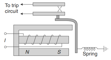
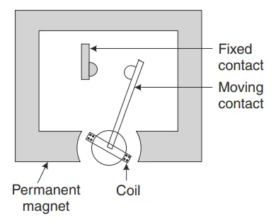
The figure shows a typical polarised moving iron relay. The construction shown in the figure is a flux shifting attracted armature type construction. Polarisation increases the sensitivity of the relay. A permanent magnet is used for polarisation. The permanent magnet produces flux in addition to the main flux. It is a dc polarised relay, meant to be used with dc only. However, it can be used with ac with rectifiers.
Modern relays have sensitivities in the range of 0.03 to 1mW, depending on their construction. Using transistor amplifiers, a relay’s sensitivity can be increased to 1 mW for pick-up.
It is used as a slave relay with rectifier bridge comparators. As its current-carrying coil is stationary, it is more robust than the moving coil type dc polarised relay. Its operating time is 2 msec to 15 msec depending upon the type of construction. An ordinary attracted armature type relay is not sensitive to the polarity of the actuating quantity whereas a dc polarised relay will only operate when the input is of the correct polarity.
6. Reed Relays
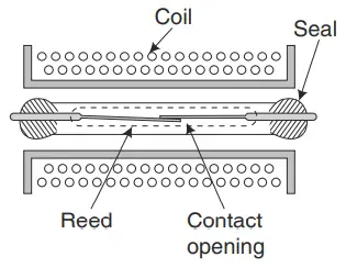
A reed relay consists of a coil and nickel-iron strips (reeds) sealed in a closed glass capsule, as shown in Figure. The coil surrounds the reed contact. When the coil is energized, a magnetic field is produced which causes the reeds to come together and close the contact. Reed relays are very reliable and are maintenance-free. As far as their construction is concerned, they are electromagnetic relays. But from the service point of view, they serve as static relays. They are used for control and other purposes. They can also be used as a protective relay. Reed relays are quite suitable to be used as slave relays.
This relay’s input requirement is 1 W to 3 W and they have a speed of 1 or 2 msec. They are completely bounce-free and are more suitable for normally closed applications. Heavy-duty reed relays can close contacts carrying 2 kW at 30 A maximum current or at a maximum of 300 V dc supply. The voltage withstands capacity for the insulation between the coil and contacts is about 2 kV. The open contacts can withstand 500 V to 1 kV.
(ii) Induction Relays
Induction relays use the electromagnetic induction principle for their operation. Their principle of operation is the same as that of a single-phase induction motor. Hence, they can be used for ac currents only.
Two types of construction of these Relays are (1) induction disc and (2) induction cup.
In both types of induction relays, the moving element such as disc or cup is equivalent to the rotor of the induction motor. There is one contrast from the induction motor, i.e., the iron associated with the rotor in the relay is stationary. The moving element acts as a carrier of rotor currents, whereas the magnetic circuit is completed through stationary magnetic elements.
1. Induction Disc Relay
There are two types of construction of induction disc relays, namely the shaded pole
type and watt-hour meter type.
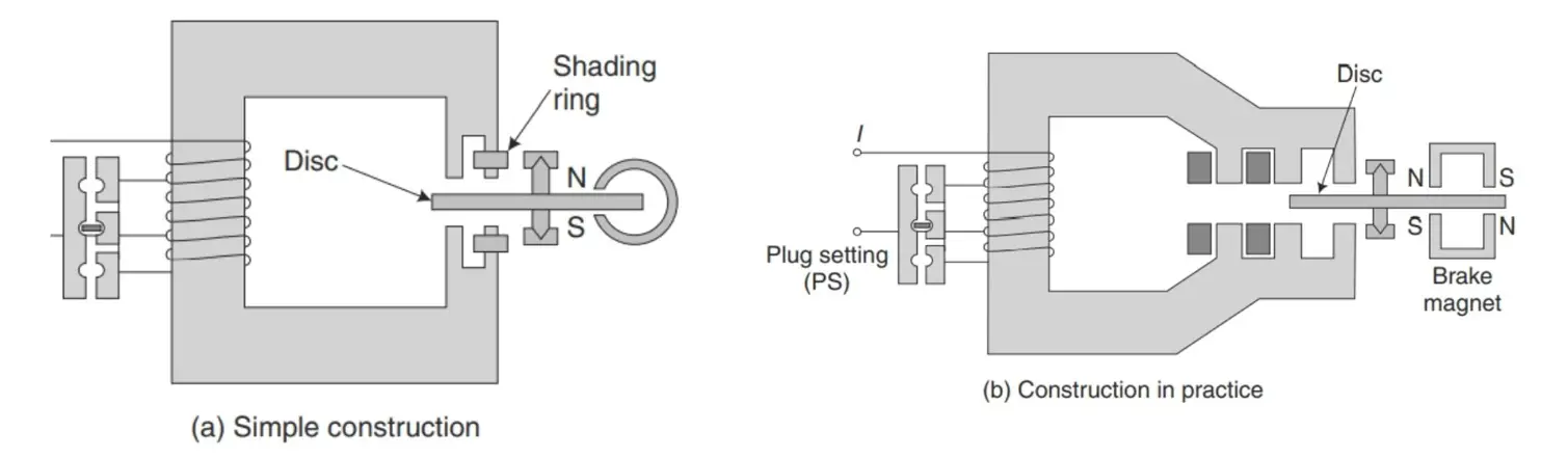
In the shaded pole type construction, a C-shaped electromagnet is used. One-half of each pole of the electromagnet is surrounded by a copper band known as the shading ring. The shaded portion of the pole produces a flux that is displaced in space and time with respect to the flux produced by the unshaded portion of the pole. Thus two alternating fluxes displaced in space and time cut the disc and produce eddy currents in it. Torques are produced by the interaction of each flux with the eddy current produced by the other flux. The resultant torque causes the disc to rotate.
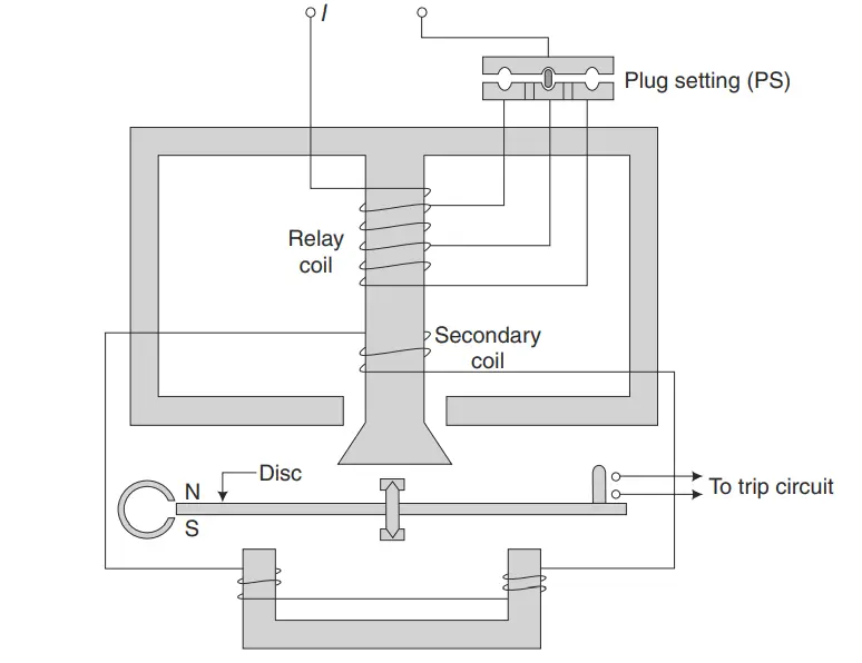
In the watt metric type of construction, two electromagnets are used: upper and lower. Each magnet produces an alternating flux which cuts the disc. To obtain a phase displacement between two fluxes produced by upper and lower electromagnets, their coils may be energized by two different sources. If they are energized by the same source, the resistances and reactances of the two circuits are made different so that there will be sufficient phase differences between the two fluxes.
2. Induction Cup Relay
The figure below shows an induction cup relay. A stationary iron core is placed inside the rotating cup to decrease the air gap without increasing inertia. The spindle of the cup carries an arm that closes contacts. A spring is employed to provide a resetting torque. When two actuating quantities are applied, one may produce an operating torque while the other may produce restraining torque. Brake magnets are not used with induction cup-type relays. It operates on the same principle as that of an induction motor with an 8-pole structure employed.
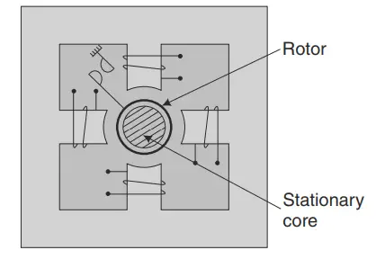
The rotor is a hollow cylinder (inverted cup). Two pairs of coils, as shown in the figure, produce a rotating field that induces a current in the rotor. Torque is produced due to the interaction between the rotating flux and the induced current, which causes rotation. The inertia of the cup is much less than that of a disc. The magnetic system is more efficient and hence the magnetic leakage in the magnetic circuit is minimum. This type of magnetic system also reduces the resistance of the induced current path in the rotor. Due to the low weight of the rotor and efficient magnetic system its torque per Volt-Ampere is about three times that of an induction disc type construction. Thus, its Volt-Ampere burden is greatly reduced. It possesses high sensitivity, high-speed and produces a steady non-vibrating torque. Its parasitic torques due to current or voltage alone are small. Its operating time is to the order of 0.01 seconds. Thus with its high torque/inertia ratio, it is quite suitable for higher speeds of operation.
Magnetic saturation can be avoided by proper design and the relay can be made to have its characteristics linear and accurate over a wide range with a very high reset to pick-up ratio. It is inherently self-compensating for dc transients. In other words, it is less sensitive to dc transients. The other system transients, as well as transients associated with CTs and relay circuits, can also be minimized by proper design. However, the magnitude of the torque is affected by the variation in the system frequency.
Induction cup-type relays were widely used for distance and directional relays. Later, they were replaced by bridge rectifier-type static relays.

 Circuit Breakers: Construction, Working, Advantages, Disadvantages & Applications")

")
 Current Feels Different to a Shock From Direct (DC) Current?")


