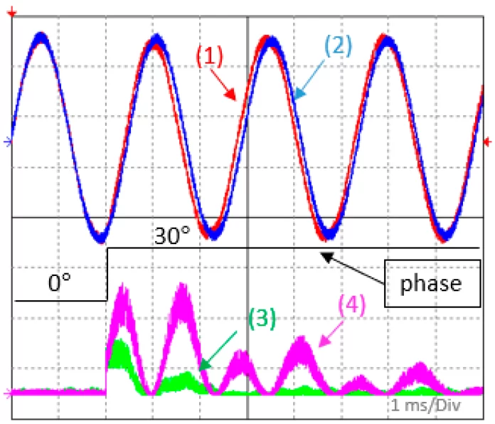
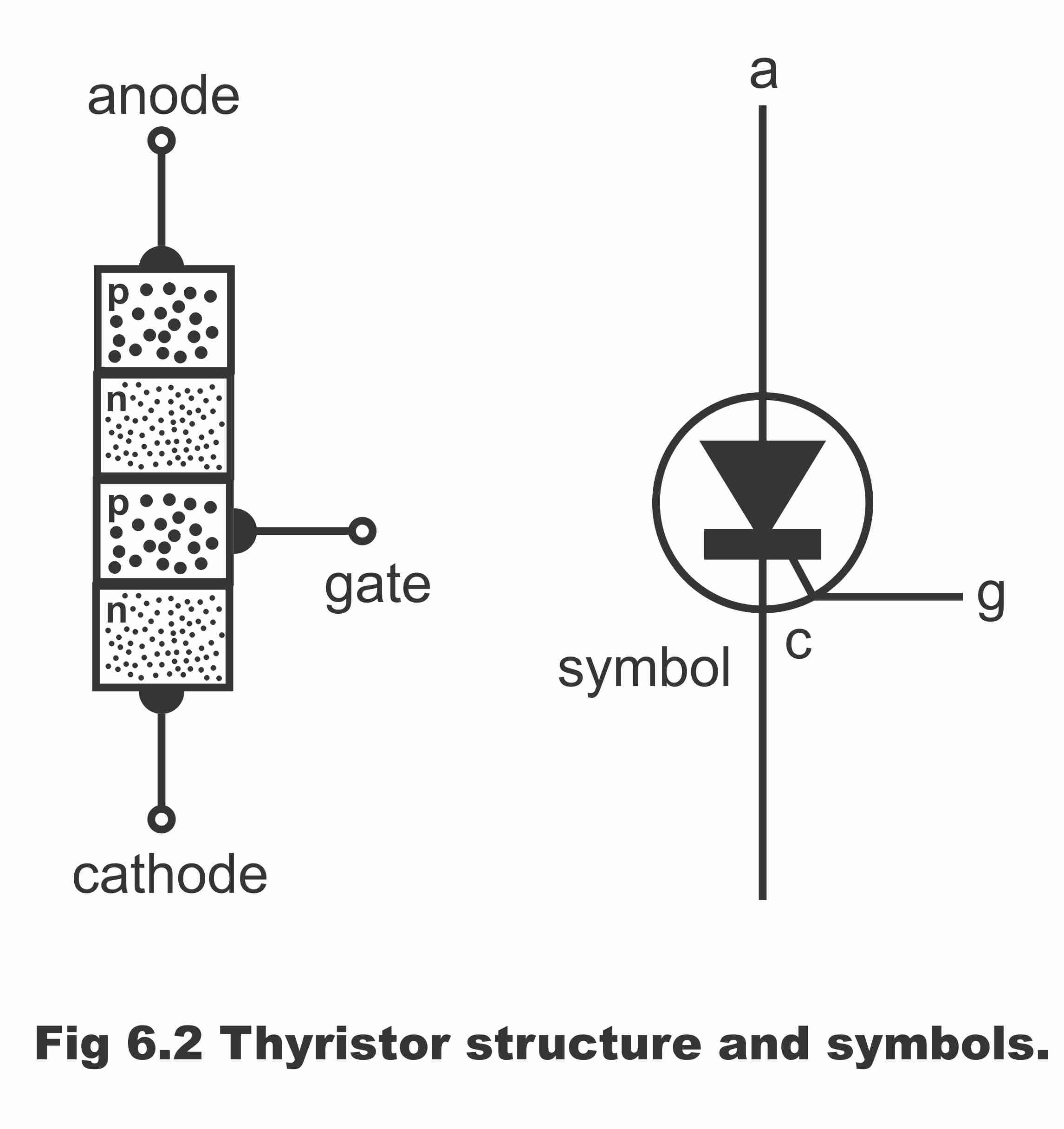
We know that there must five conditions that must be met before the synchronization process takes place. The source (generator or sub-network) must have equal root-mean-square voltage, frequency, phase sequence, phase angle, and waveform to that of the system to which it is being synchronized. [1]
In order to synchronize an alternator to an existing three-phase power line, the following conditions must be satisfied:
- Frequency: The frequency of the alternator must be the same as that of the power line. The frequency of the power line is typically 50 Hz or 60 Hz, depending on the country. In India, we use 50Hz.
- Voltage: The voltage of the alternator must be the same as or slightly higher than that of the power line.
- Phase sequence: The phase sequence of the alternator must match that of the power line. This means that the phases of the alternator must be in the same order as the phases of the power line.
- Phase angle: The phase angle of the alternator must be the same as that of the power line. This means that the voltage waveform of the alternator must be synchronized with the voltage waveform of the power line.
To synchronize the alternator to the power line, the alternator’s speed and voltage must be adjusted until the voltage waveform of the alternator is in phase with the voltage waveform of the power line. This is typically done using a synchronizing relay, which monitors the phase angle and voltage difference between the alternator and the power line and adjusts the alternator’s output accordingly. Once the alternator is synchronized with the power line, it can be connected to the power grid and begin supplying power.
Several methods for synchronizing an alternator with a three-phase power line
There are several methods for synchronizing an alternator with a three-phase power line, including:
- Synchroscope method: This method uses a synchroscope, which is a device that indicates the difference in phase angle between the voltage waveform of the alternator and the voltage waveform of the power line. The operator adjusts the alternator’s speed until the synchroscope needle rotates slowly, indicating that the phase angle difference is approaching zero. Once the needle stops rotating and remains stationary, the operator knows that the alternator is synchronized with the power line.
- Dark lamp method: This method involves connecting a small lamp in series with the alternator’s output and the power line. When the alternator’s voltage is out of phase with the power line, the lamp will flicker or go dark. The operator adjusts the alternator’s speed until the lamp remains steadily lit, indicating that the alternator is synchronized with the power line.
- Three-voltmeter method: This method uses three voltmeters to measure the voltage difference between each phase of the alternator and the corresponding phase of the power line. The operator adjusts the alternator’s speed until the voltage difference is minimized, indicating that the alternator is synchronized with the power line.
- Automatic synchronizing relay method: This method uses a synchronizing relay that automatically adjusts the alternator’s output voltage and frequency until it matches that of the power line. The synchronizing relay measures the voltage and frequency of the power line and the alternator and makes adjustments as necessary to synchronize the two sources.
References:
-
-
- https://en.wikipedia.org/wiki/Synchronization_(alternating_current)
-


