
In many industrial applications, the control of the output voltage of inverters is necessary for the following reasons (a) to deal with the variation of dc output voltage, (b) to regulate the voltage of inverters, and lastly (c) to satisfy the constant volts-frequency control requirement.
The most efficient method of controlling the output voltage is to incorporate PWM control within the inverter. The most commonly used techniques are:
- Single-pulse-Width modulation
- Multiple-pulse-width modulation
- Sinusoidal pulse-width modulation (SPWM)
- Modified sinusoidal pulse-width modulation
- Phase-displacement control
Let us now have a look at each modulation technique one by one.
1. Single-Pulse Width Modulation
Single-pulse-width modulation (SPWM) is a type of pulse-width modulation (PWM) technique that generates a single pulse for each cycle of the AC waveform.
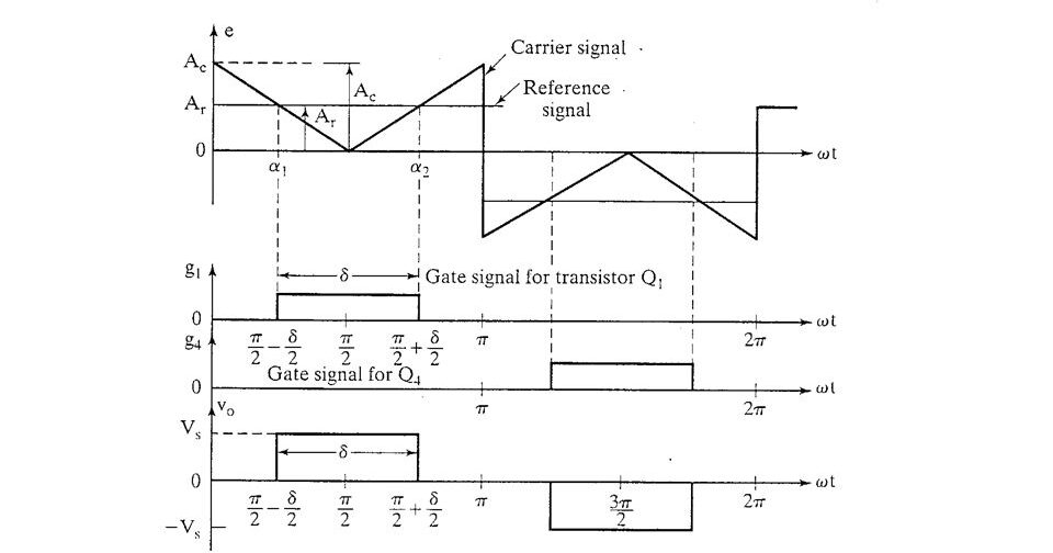 In SPWM, a carrier waveform is compared with a reference waveform to generate the modulated waveform. The reference waveform is typically a sine wave, which is used to determine the frequency and amplitude of the output waveform. Whereas, The width of the gate pulse is determined by the intersecting point of the reference signal and triangular signal.
One of the advantages of SPWM is that it is a simple technique that can be implemented using low-cost hardware. However, it can cause harmonic distortion in the output waveform, particularly when the modulation frequency is low. Therefore, it is important to carefully design and control the system to minimize the distortion caused by SPWM.
2. Multiple-pulse-width modulation
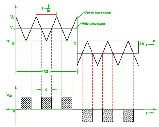 Multiple-pulse width modulation is when several pulses are produced in each half cycle of the output voltages. This type of PWM is basically used in order to reduce the harmonics contents and to increase the harmonics frequencies so that the size and cost of filtering can be reduced.
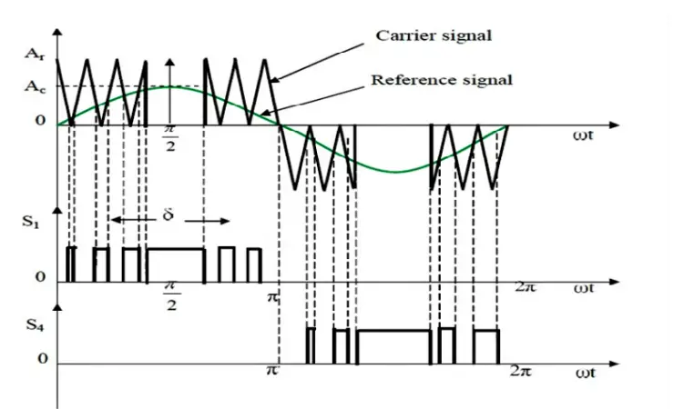
The generation of gating signals for turning the transistor ON and OFF is shown in the figure by comparing the reference signal with the triangular carrier wave.
It is understood that the frequency of the reference signal determines the output frequency (fo) whereas the frequency of the carrier signal determines the number of pulses per half cycle (P).
The number of pulses per half-cycle is found from-
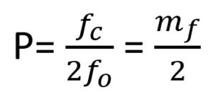
Where mƒ=ƒc/ƒo is defined as the frequency modulation ratio.
3. Sinusoidal Pulse-Width Modulation
Sinusoidal Pulse Width Modulation (SPWM) is a technique used to generate a desired sinusoidal waveform with the help of comparing the reference waveform and a carrier signal. The square wave or triangular wave is used as a carrier signal, and its pulse width is varied to produce a sinusoidal waveform.
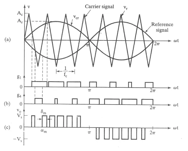 The SPWM is commonly used in industrial applications. The frequency of the reference signal (fr) determines the inverter output frequency (fo), and the peak amplitude of the reference signal controls the modulation index (M) and RMS output voltage (Vo).
The RMS output voltage can be varied by varying the modulation index which is defined by M=Ar/Ac. It is to remember that the gating signal of the switches can be generated by a unidirectional carrier signal or the bidirectional signal.
In this modulation technique, the switching losses, the Distortion Factor (DF), and Low Order Harmonics (LOH) are reduced completely compared to multiple-pulse modulation.
However, SPWM also has some limitations such as difficulty in maintaining a constant amplitude under changing load conditions, and the potential for audible noise due to the switching of the carrier signal.
4. Modified sinusoidal pulse-width modulation
We have read the modulation technique of SPWM and how the sinusoidal output is obtained. The modified sinusoidal pulse-width modulation (MSPWM) is a modified version of sinusoidal pulse width modulation (SPWM), which is a widely used technique in power electronics.
 The sinusoidal pulse width modulation can be modified so that the carrier wave is applied during the first and last 60° intervals per half-cycle (e.g, 0° to 60° and 120° to 180°). And the intervals can vary as per the requirements. The modified sinusoidal pulse-width modulation (MSPWM) is shown below:
The main advantages of MSPWM are that the fundamental components are increased and its harmonics characteristics are improved. It also reduces the number of switching devices and also reduced the switching losses.
5. Phase-displacement control
 Phase displacement control is a technique used in power electronics to control the phase angle between the voltage and current in an AC circuit. It is a type of phase control that can be used to control the amount of power delivered to a load.
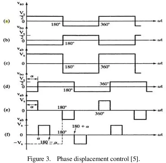
A 180° phase displacement produces an output voltage as shown in the above figure (c), whereas the delay (or displacement) angle of α (alpha) produces an output in figure (e).
For example, the gate signal g1 for the half-bridge inverter can be delayed by angle α (alpha) to produce gate signal g2.
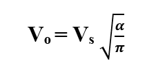
RMS Output Voltage is given by,
Hope the reference and details are clear, if you have any doubts or confusion feel free to comment. we will respond to you right away.
")


")
 Current Feels Different to a Shock From Direct (DC) Current?")


