In this piece of content, we are going to study the thyristor chopper circuits including their commutation circuitry.
We know that so far chopper is shown as a switch and also a chopper consists of a main power semiconductor device that can turn-on and turn-off. To be more precise, the use of semiconductor devices inside has its own properties and characteristics. Therefore, the use of devices like power transistors, GTOs, thyristors, etc. have two scenarios.
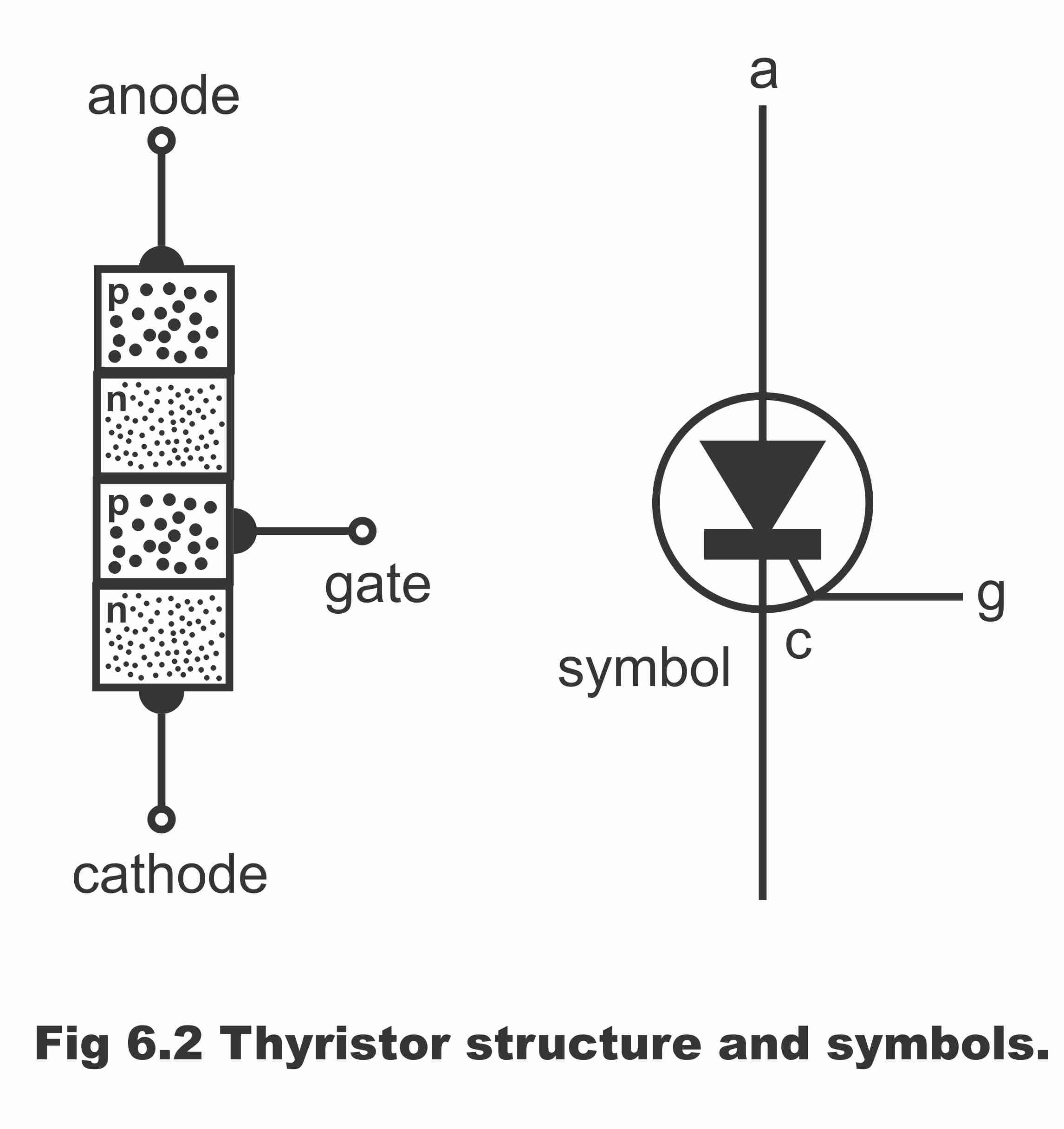
First of all, In low power chopper circuits, power transistors, GTOs, etc. are being broadly used. However, in high-power chopper circuits, thyristor is commonly used.
Commutation is the process of opening or turning off a conducting thyristor. In the DC chopper, it is necessary to provide a separate commutation circuitry to commutate the main power SCR. Note that the conducting thyristor can be turned off by reducing the current in the anode below the holding current value and the by reversing the voltage across the device and enabling the forward blocking capability.
There is a different way that you can turn off the thyristor. In dc chopper, commutation circuits have a number of innovations and are broadly classified into two groups: (a) Forced Commutation, and (b) Load Commutation.
(a) Forced Commutation
In forced commutation, external elements such as inductor ‘L’ and capacitor ‘C’ which do not carry the load current continuously, are used to turn off a conducting thyristor. Forced commutation can be achieved by following two ways: (i) Voltage commutation and (ii) Current commutation
(i) Voltage commutation
In this scheme, a conducting thyristor is commutated by the application of a pulse of a large reverse type of voltage. This reverse voltage is usually applied by switching a previously charged capacitor from the circuit device. The sudden application of the reverse voltage across the conducting thyristor reduces the anode current to zero rapidly. Then the presence of a reverse voltage across the SCR aids in the completion of its turn-off process (i,e. aids in gaining the forward blocking capability of SCR).
(ii) Current commutation
In this scheme or thyristor chopper circuits, an external pulse of current greater than the load current is passed in the reversed direction through the conducting SCR. When the current pulse attains a value equal to the load current, the net pulse current through the thyristor becomes zero and the device turn off. So the current pulse is usually generated by an initially charged capacitor.
An important feature of current commutation is the connection of a diode in anti-parallel with the main thyristor so that voltage drop across the diode reverse biases the main SCR. Since this voltage drop is of the order of is 1 volt, the commutation time in the current commutation is more as compared to that in voltage commutation.
In both voltage and current commutation schemes, commutation is initiated by gating an auxiliary SCR.
Load commutation
In thyristor chopper circuits namely load commutation, a conducting thyristor is turned off when load current flowing through a thyristor either:


![Thyristor Chopper Circuits [Notes & Example] Thyristor Chopper Circuits](https://electricalguide360.com/wp-content/uploads/2021/11/Thyristor-Chopper-Circuits-Notes-Example-696x392.jpg)


Where this article states “However, in low-power chopper circuits, thyristor is commonly used.”, should that not actually state “high power” instead of “low-power”?
Hi, Fraser Johnson. You point it out right! After cross-checking various references we have updated it again. Thanks for your concern and apologize for the misinterpretation.