

In chopper circuits, unidirectional power semiconductors devices are used. There is a restriction between the polarities of output voltages Vo and the direction of output current Io. However, a chopper can be used in any four quadrants by arranging the semiconductor devices appropriately.
So, these four-quadrant operational characteristics classified the flowing types of chopper circuits, namely:
1. First-quadrant, or Type-A Chopper
2. Second-quadrant, or Type-B Chopper
3. Two-quadrant type-a, or Type-C Chopper
4. Two-quadrant type-b, or Type-D Chopper
5. four-quadrant Chopper, or Type-E Chopper
In the configuration of chopper-circuits, the direction of current and voltage polarities in the power circuit would always be treated as positive. But if the current direction and voltage polarity turned out to be opposite, then both the current and voltage is treated as negative.
Different Types of Chopper Circuits
Let’s now study more in detail about its types of chopper circuits…
1. First-quadrant, or Type-A Chopper
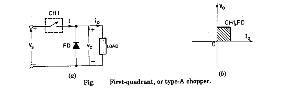
The first-quadrant or Type-A Chopper circuit is shown in the figure. From figure 1(a), when chopper in ON condition, then Vo=Vs and the direction of flow of current (io) is given by an arrow. Again, when Chopper is in OFF condition, Vo=0, however, the direction of current (io) remains unchanged i.e., it will flow through the freewheeling diode, FD. As shown in the Vo-io plane [in figure 1(b)], we can see that the average voltages (Vo) and load current (io) are always positives. Note that power flow in type-A is always from source to load. This type of chopper is also called a step-down chopper due to the fact that the output average voltage (Vo) is lesser than that of the input voltage (Vs).
2. Second-quadrant, or Type-B Chopper
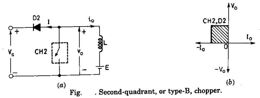
The circuit for this type of chopper is shown in figure 2 (a). Here, the load must contain the dc source ‘E’, like a battery (or a dc motor) in this chopper. When the chopper (CH2) is in ON condition, Vo=0. But the load voltage ‘E’ will drive a current through ‘L’ and chopper (CH2). The inductance(L) will store energy when the chopper is in Ton Period.
When the chopper is in OFF condition, vo=E + L di/dt. Here, since the value of Vo exceeds the supply voltage (Vs). As a result, the diode D2 will be forward biased and will be conduction which will allow the power to flow to the source.
Now, The chopper may be in ON or OFF condition, the current flow (io) will be out of the load, as a result, the current flow will be treated as negative. Here, since Vo is always positive and io is negative, the power flow will be from load to source.
Lastly, as the average output voltage (vo) is more than sour or supply voltage, this Type-B Chopper is called a step-up chopper.
3. Two-quadrant type-A, or Type-C Chopper
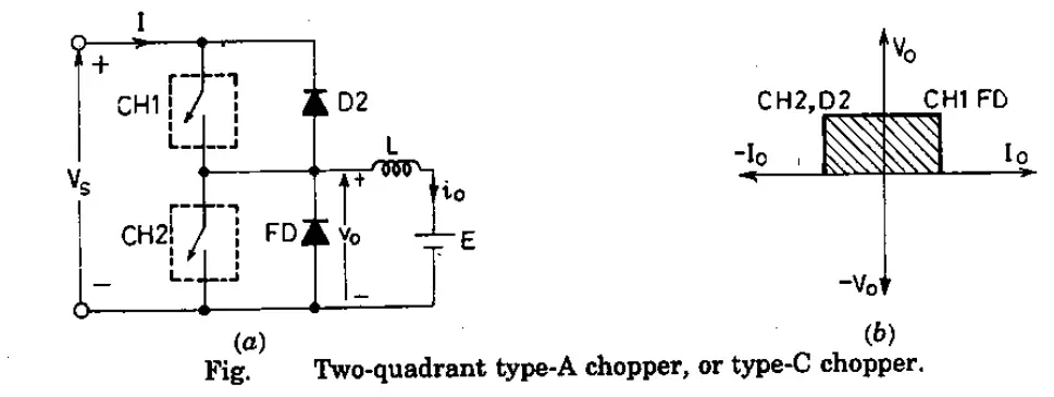
In this types of Chopper Circuits, Type-A and Type-B are connected in parallel as shown in figure 3(a). Due to the presence of freewheeling diode FD across the load, the output voltage (Vo) is always positive. When the chopper CH2 is turned ON, the freewheeling diode FD conducts and thus obtaining the output voltage, vo=0. Similarly, When the chopper CH1 is turned ON, the diode D1 conducts and the output voltage is given by vo=Vs.
The current io flows in the arrow direction as shown in figure 3(a). Note that the load current can however be in reversed condition. So, we can say that the load current is positive when the chopper CH1 is at ON condition and freewheeling diodes conducts. And, the load current is negative if the chopper CH2 is at OFF condition or when D2 conducts. In other words, chopper CH1 and freewheeling diode FD operate as Type-A choppers in the first quadrant, and similarly, chopper CH2 and D2 operate together as Type-B in the second quadrant.
The average load voltage is always positive but the average load current may be either positive or negative as discussed above. Therefore, power flow may be from the source to load (first-quadrant operation) and from load to a source (second-quadrant operation).
Note that the chopper CH1 and CH2 should not be operated or turned ON at the same time as this would lead to a direct short circuit on the supply lines. This type of chopper is basically used for monitoring and regenerative braking of a DC motor. the operating region is first-quadrant and second-quadrant as shown in figure 3(b).
4. Two-quadrant type-B, or Type-D Chopper
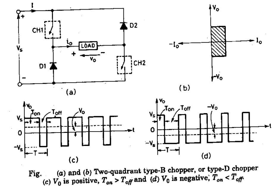
The power circuit diagram of Two-quadrant type-b or Type-D Chopper is shown in figure 4(a). When both the chopper CH1 and CH2 are at ON condition then the output average voltage vo=Vs. When both the chopper is turned OFF but diodes D1 and D2 conduct, then the output voltage vo=-Vs. The average output voltage is positive when the chopper turn-on time (Ton) is more than their turned-off (Toff) time i.e., Ton>Toff. Similarly, the average output voltage will be negative when the chopper turn-on time (Ton) is less than their turned-off (Toff) time i.e., Ton<Toff.
The direction of the flow of load current will always remain positive because chopper and diodes can conduct only in the direction as shown in figure 4(a). As the output voltage Vo is reversible, therefore the power flow is also reversible. The operation of this type of chopper characteristic is represented by a hatched area in the first quadrant and fourth quadrant shown in figure 4(b).
5. four-quadrant Chopper, or Type-E Chopper
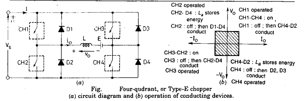
The power circuit diagram of the four-quadrant Chopper or Type-E Chopper is shown in figure 5(a). This types of Chopper Circuits consists of four semiconductor switches CH1 to CH4 and four diodes D1 to D4 anti-parallel. The working of this chopper is explained under four quadrants.
- First-quadrant:- The operation of the first quadrant is shown in figure 5(a). When the CH4 is turned ON, CH3 remains OFF and CH1 gets operated. As CH1 and CH4 are at ON condition, the load voltage is equal to the source voltage (Vo=Vs) and the load current begins to flow in the circuit. When CH1 is turned off, a positive current flows through CH4 and D2. In this way, we can control the load voltage (Vo) and load current (Io).
- Second-quadrant:- Here CH1, CH3, CH4 are kept off and CH2 is being operated. As CH2 is turned ON, reverse (or negative) current flows through L, CH2, D4, and E. Inductance (L) is used to store energy when the CH2 is turned ON. When CH2 is turned off, the current is feedback to the source through diode D1 and D4. Here output voltage is more the supply voltage (Vo=Vs). In the second quadrant, the load voltage is positive and the load current is negative. Note that the power feedback is from load to source.
Also Learn: DC Chopper or DC-to-DC Converter: Working & its Function
- Third-quadrant:- The operation of the third-quadrant is shown in figure 5 (a). Here, CH1 is kept off, CH2 is kept ON and CH3 is being operated. The polarity of the load emf E is reverse for working in this quadrant. With CH3 being operated, the load gets connected to the source (Vs) so that both load voltage (Vo) and load current (Io) are negative leading to third quadrant operation. When CH3 turned OFF, negative current freewheels through the CH2 and D4. So, in this way, Vo and Io are controlled in the third quadrant.
- Fourth-quadrant:- In this quadrant, CH4 is operated and other devices or parts are kept off. Load Emf E must have its reverse polarity for operation in the fourth quadrant as shown in figure 5(a). With CH4 kept ON mode, positive current flows through CH4, D2, L, and E. Here inductance ‘L’ stores energy when CH4 is turned ON. When CH4 is turned off current is feedback to the source through diode D2 and D3. Here, the load voltage is negative, but the load current is positive leading to the chopper operation in the fourth quadrant. Note that power feedback is from load to source. The operation of conducting devices in the fourth quadrant is shown in figure 5(b).
")


")
 Current Feels Different to a Shock From Direct (DC) Current?")


