

Definition:- A DC Chopper or DC-to-DC Converter is a static power electronics device that converts fixed dc input directly into a variable dc output voltage.
This conversion of dc to dc voltage through the use of semiconductor devices can be done in two ways:
1. AC Link Chopper:- In this method, DC is first converted to AC with the help of an inverter (dc to ac converter) and finally the AC is converted back to DC using a diode rectifier.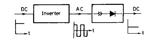 So, it is just the process of converting DC to DC with the AC involved in between. As observed, it is a two-stage conversion due to which this method is costly, bulky, and less efficient.
2. DC Chopper:- As mentioned in the definition, A DC Chopper or DC-to-DC Converter is a static power electronics device that converts fixed dc input to a variable dc output voltage directly. This is the most efficient method as it involved only a one-stage conversion.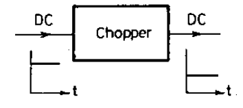 Like a transformer, a dc chopper also can be used to step-down or step-up the fixed dc input. So, there is a Step-down dc chopper and a step-up dc chopper. Out of these two, the step-down dc chopper is the most commonly used.
Let us now study the principle operation of the DC chopper…
Principle Operation of the DC Chopper
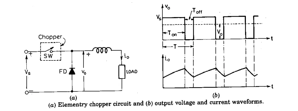
A DC Chopper is a high-speed switching semiconductor device. It connects and disconnects the source and loads at a fast speed. The figure below shows the circuit of the DC chopper (fig. a) and Output current along with the current waveform (in fig. b).
In fig (a) the circuit diagram of a DC chopper is shown. Vs represents the supply dc voltage and the chopper is represented by a switch in the rectangular form. FD represents the freewheeling diode and Vo is the load voltage.
When a DC chopper is turned on (i.e during Ton cycle) the load voltage (Vo) is equal to the supplied voltage (Vs). Again, during the Toff cycle, the chopper is in OFF condition, and load current will flow through the FD (Freewheeling diode). Therefore, the load terminal will be short-circuited and as a result, there will be zero load voltages flowing through the load. So, this is how the chopped dc voltages are obtained in the load terminal. Note that the load current in fig (b) is continuous.
From fig (b), the average load voltage (Vo) is given by
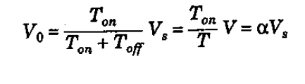
So, the load can be controlled by varying duty cycle ‘α’ (alpha). Also we from the equation above we can say that voltage is independent of the load current. Furthermore, the above top equation can be written as:

Step-Down DC Chopper (Buck Converter)
When the average output voltage (Vo) is lesser than the supply voltage (Vs) i.e, Vo< Vs then the chopper is known as Step-down DC Chopper. This step-down DC Chopper is also commonly known as a buck converter.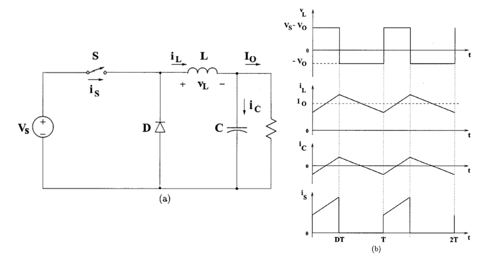 The circuit diagram is shown in figure (a). It consists of dc input voltage source (Vs), controlled switch (S), diode (D), filter inductor (L), filter capacitor (C), and load resistance (R). The waveform of the converter is shown in figure (b). The waveform is obtained with an assumption that the inductor current is positive. This means that the inductor current always has some value and is never zero which is called continuous conduction mode.
Step-Up DC Chopper (Boost Converter)
When the average output voltage (Vo) is greater than the supply voltage (Vs) i.e, Vo> Vs then the copper is known as step-up dc chopper. It is also known as Boost Converter.
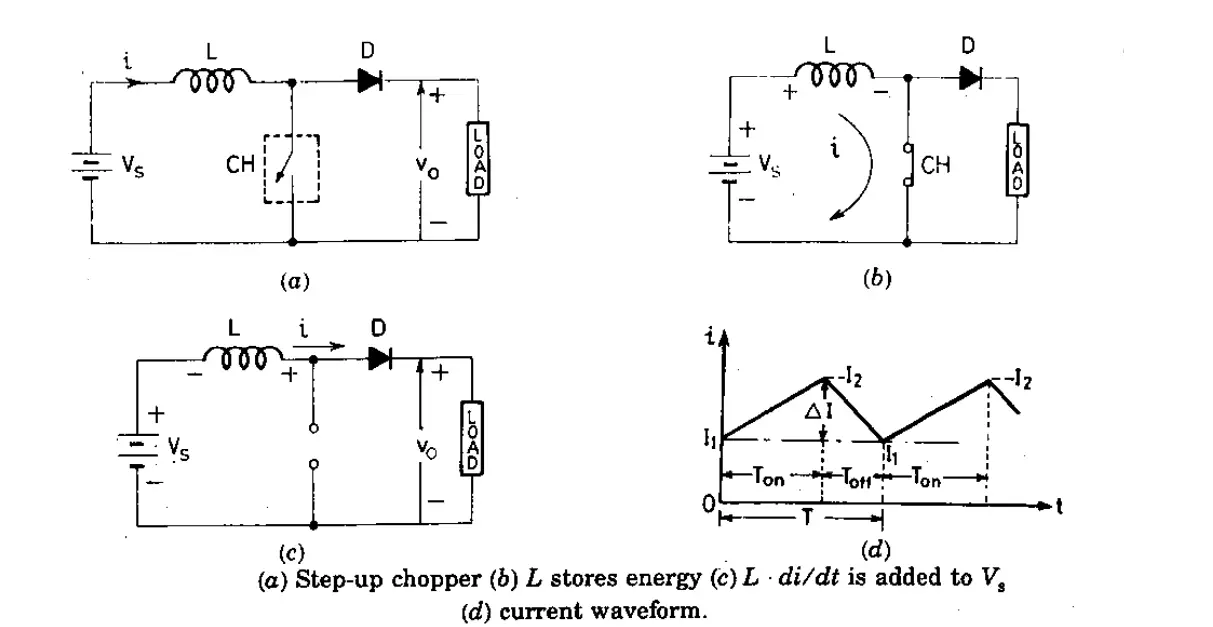
Figure (a) represents the normal step-up dc chopper diagram.
When the DC chopper (CH) is turned ON (i.e during Ton period) as shown in fig (b), the inductor will store energy. This simply means the current flow across the load. Now, when the DC chopper (CH) is turned Off (i.e during Toff period) as shown in fig (c), the inductor gradually has a low capability of storing the energy, and the current is forced to flow through the diode. As the current tends to decrease, the polarity of the emf induced in L is reversed as shown in fig (c). As a result voltage, across the load, is given by Vo=Vs+L(di/dt), which exceeds the source voltage Vs. So, in this way, the DC Chopper acts as a step-up dc chopper, and the energy which is stored in the inductor is released to the load.
In figure (d), when the chopper (CH) is ON, the current through the load increase from I1 to I2, and when the chopper (CH) is OFF, the current falls from I2 to I1.
Types Of Chopper Circuit
Depending on the classification of Chopper configuration, DC-DC Converter or DC Chopper is for five types:-
1. First-quadrant, or Type-A Chopper
2. Second-quadrant, or Type-B Chopper
3. Two-quadrant type-a, or Type-C Chopper
4. Two-quadrant type-b, or Type-D Chopper
5. four-quadrant Chopper, or Type-E Chopper
Also Check: Types Of Chopper Circuit [In Details]
Types of Control Strategies in DC Chopper
In a DC-DC converter, the output voltage can be controlled through duty cycle ‘α’ (alpha) by opening and closing the semiconductor switch periodically. So, various control of the duty cycle (α) can be done in three methods: (1) Constant Frequency System, (2) Variable Frequency System, and (3) Current Control Limit (CLC).
1. Constant Frequency System
In this type of control scheme, the chopping frequency ‘f’ (or chopping period T) is kept constant whereas the Ton (On-time) is varied. Varying Ton means adjusting the pulse width, that is why this scheme is also called pulse width modulation. Some authors called it time-ratio control (TRC).
2. Variable Frequency System
In this scheme, unlike the constant frequency system, the chopping frequency f is kept constant and either Ton (on-time) or Toff (off-time) is kept constant. This method of controlling the duty cycle (α) is called the frequency-modulation scheme.
As variable frequency system has few disadvantages, therefore, the constant frequency (PWM) scheme is better than the Variable-Frequency system. However, there are a few limitations such as for most of the commutation techniques used in dc chopper, the Ton cannot be reduced to zero. Also in PWM, low range of duty cycle (α) control is not possible. But all these limitations can be achieved or fulfilled by increasing the chopping period (or decreasing chopping frequency) of the chopper.
3. Current Control Limit (CLC)
Current Limit Control or CLC is another method to control the output voltage of the DC Chopper. In this technique, the dc chopper is turned ON when the output current i0 equals a preset value I2 and the chopper is kept ON till I0 increases to another preset value I1. The maximum and minimum set values of load current are Iomax and Iomin respectively. The value of these Iomax and Iomin are independent of each other.
Advantages
The advantages of the DC chopper are as given below:
- It has good efficiency.
- It is used in isolating the primary and secondary circuits from each other when needed.
- It is used in voltage regulation.
- It has a smooth dc voltage control.
- It has a quick response.
- It requires less maintenance.
- Its cost is less than motor-generator sets.
- It requires less space as its size can be reduced by a converter.
Disadvantages
- Switching converters lead to more noise.
- They are expensive as an external circuit is required.
- Choppers are inadequate due to unsteady voltage and current supply.
- More ripple current, More input and output capacitance, higher losses, etc.
Applications of DC-to-DC Converter
- It is used in portable electronic devices such as cellular phones and laptop computers and other electronic devices. The power supply for all these devices is primarily from Batteries.
- Switched DC to DC converters is used for increasing the voltage from the low battery voltage. Therefore, no need of using multiple batteries for achieving the same thing.
- DC-to-DC converter circuits are used for voltage regulation in the output. For example, an LED Power Source that regulates the current through the LEDs. Also, a simple charge pump which double or triple the output voltage.
- It is designed in order to maximize the energy harvest for photovoltaic systems and for wind turbines are called power optimizers.
- DC-to-DC converters are commonly used in DC microgrid applications, where different voltages levels are required.
")


")
 Current Feels Different to a Shock From Direct (DC) Current?")


