

We know that there are two types of Generators in electrical machines that is AC Generator (Or Alternator) and DC Generator.
AC Generator works with Alternating Current which produces Alternating Power whereas DC generator works with Direct current which gives out Direct power. The article outlines only DC generators.
Let’s learn…
DC Generator Working Principle
A dc electric generator is simply a machine that converts mechanical energy into dc electrical energy.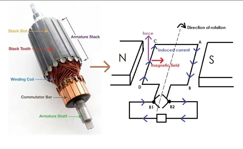
The working principle of an electric generator is based on the principle of the faradays law of electromagnetic induction, it states that whenever a conductor is placed in a moving magnetic field, an e.m.f. is induced in a conductor which will cause a current to flow in the conductor, provided the circuit has to be closed circuit. The direction of induced e.m.f. (or current) is given by Fleming’s right-hand rule.
Under this working principle, there is two part of the mechanism that we need to understand i.e Simple close loop, and the second is about the action of commuters.
Simple Loop Generator
Let us consider a loop ABCD rotating clockwise in a uniform magnetic field with a constant speed as shown in Figure A. As the loop rotates, the flux starts linking to the coil side AB, and CD changes continuously. So, the e.m.f. that is induced in these coil sides will also change.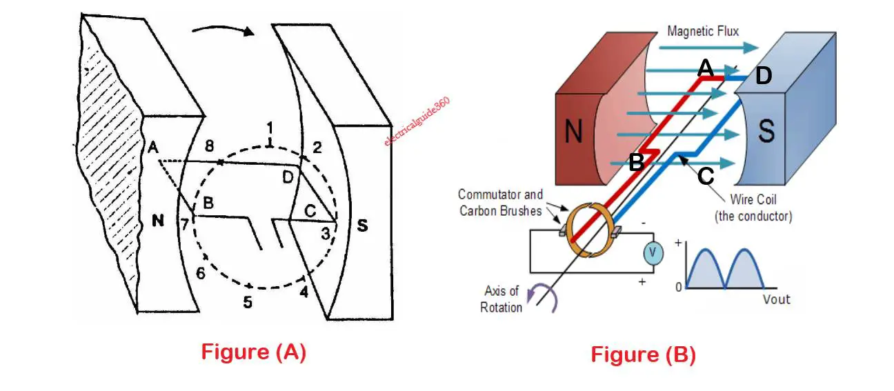
(i) In figure A, When the loop is at position no. 1, the generated e.m.f. is zero because the coil sides (AB and CD) still did not cut any flux and is in a parallel position with the poles.
(ii) When the loop is at position no. 2, the coil sides are moving at some angle to the flux and, therefore, a low e.m.f. is generated.
(iii) When the loop is at position no. 3, the coil sides (AB and CD) are at the right angle which cuts the flux at the maximum rate. Hence at this point, the generated e.m.f. is maximum.
(iv) When the loop is at position no. 4, the coil side again cut the flux at some angle therefore the generated e.m.f. is less.
(v) When the loop is at position 5, again no magnetic lines are cut because it is parallel to the pole, and hence induced e.m.f. is zero.
(vi) When the coil is at position 6, the direction of generated e.m.f. is reversed because the coil sides move under a pole of opposite polarity.
(vii) When the coil is at position no 7, There will be again maximum e.m.f. in this direction (i.e., reverse direction). It is because the right angle is formed between the coil to that of flux. And again at position 1, there will be no e.m.f produced.
This cycle will repeat in each revolution of the coil.
Note that e.m.f. generated in the loop is alternating one which thus forms alternating voltage and if the load is connected then alternating current will flow through the load. Now, The alternating voltage which is generated in the loop is converted into direct voltage by a device called the commutator. Therefore, the d.c generator will obtain after overall conversion. Also, note that a commutator is a mechanical rectifier.
Action Of Commutator
We have already known that a commutator can convert alternating voltage to direct voltage thus forming dc current when the load is connected. Here we will more understand the mechanism and function of the commutator.
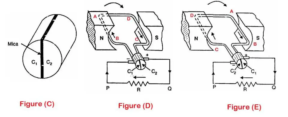 Figure (C) shows that a commutator has two segments namely C1 and C2 separated by a thin sheet of mica. The coil side AB is connected to segment C1 similarly coil side CD is connected to segmentC2 respectively. There are stationary brushes connected to the load. S-pole has +ve brush whereas N-pole has +ve brush.
In Figure (D), the coil sides AB which is connected to segment C1 is under N-pole and similarly, the coil sides CD which is connected to segment C2 is under S-pole. Segments C1 and C2 are connected to terminal P and Q of load resistance R, respectively.
When the coil completes half revolution (i.e 180° rotation), the position of the coil changes i.e AB and CD are now under S-pole and N-pole respectively (See figure E). Now, the current is in the reverse direction. Also, the commutator segment moves to 180° (C1 comes at +ve brush and segment C2 comes to -ve brush). The commutator has now reversed the coil connections to the load i.e., coil side AB is now connected to terminal Q of the load and coil side CD to the terminal P of the load. So, the direction of current is again from Q to P.
Thus the alternating voltage generated in the loop will appear as the direct voltage
across the brushes. Note that e.m.f in the armature winding is alternating one. But with the help of the commutator, the generated alternating e.m.f get converted to direct voltage.
The purpose of brushes is simply to lead current from the rotating loop or winding to the
external stationary load.
Also see: DC Chopper or DC-to-DC Converter: Working & its Function
Construction of D.C Generator
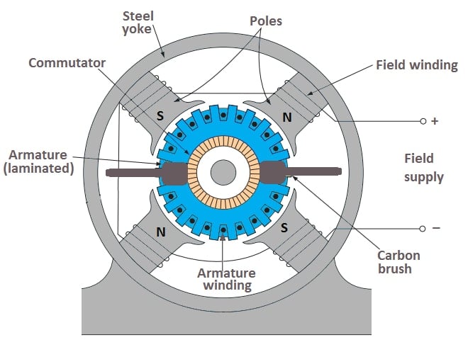
Generally, the construction of d.c. generators and d.c. motors are the same. A DC generator can be used as a DC motor and vice-versa. All d.c. machines have five main components viz., (i)Field system (ii) Armature core (iii) Armature winding (iv) Commutator (v) Brushes.
(i) Field system
The purpose of the field system is used to generate a uniform magnetic field. It consists of a number of salient poles (Number of poles must be even number) and generally, we called it yokes. The yoke is made of solid cast steel whereas the pole pieces are composed of stacked laminations.
(ii) Armature core
The armature core is mounted to the machine shaft and rotates between the field poles. It consists of slotted soft-iron laminations (about 0.4 to 0.6 mm thick) that are stacked to form a cylindrical core. The conductor is laminated with a thin insulating film so as to avoid electrical contact with each other. The purpose of laminating the core is to minimize the eddy current loss.
(iii) Armature winding
The insulated conductor which is suitably adjusted or placed in the slot of the armature core is known as armature winding. It is the winding in which generated e.m.f. is induced. The armature conductors are always connected in series-parallel; the conductors are connected in series so as to increase the voltage and in parallel paths so as to increase the current.
(iv) Commutator
As discussed above, a commutator is a mechanical rectifier that converts generated alternating voltage(in windings) into a direct voltage across the brushes. The commutator is composed of two copper segments and is insulated from each other by mica sheets. The commutator is mounted on the shaft of the generator.
(v) Brushes
The brushes maintain and ensure electrical connections between the rotating commutator and stationary external load circuit.
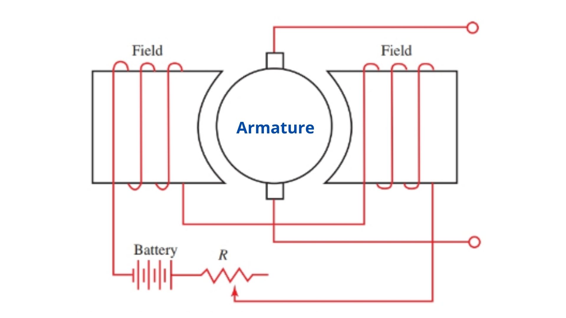
Diagram of DC Generator
A Simple Diagram of the DC generator is given below:
Learn more: 150+ V. Important Synchronous Motor MCQ Questions and Answers
EMF Equation of DC Generator
Now we have to learn how the emf is produced and induced in the coil. So, the induced e.m.f. in the conductor is given by;
e = Blv volts
where, B = magnetic flux density in Wb/m2
l = length of the conductor in meters.
v = velocity (in m/s) of the conductor
Types Of DC Generator
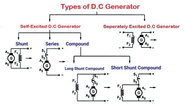
There are two types of DC generators on the basis of field excitation. Note that the magnetic field is produced by an electromagnet rather than a permanent magnet. The two types of DC generators are:-
(i) Separately excited d.c. generators
(ii) Self-excited d.c. generators
Again, there are three types of self-excited d.c generators based on how the field winding is
connected to the armature, namely;
(a) Series generator
(b) Shunt generator
(c) Compound generator
The types of DC Generator are fully explained here: Types of D.C. Generators
Important Frequently Ask Questions (FAQs)
1. The nature of the current flowing in the armature of the DC machine is:
ANSWER:- Alternating Current or AC. In the armature of the DC machine, the current flow direction will be alternating manner. This alternating current is made unidirectional with the help of the Commutator. This is the main use of the commutator in the DC machine.
2. Fleming’s left-hand rule is applicable for:
ANSWER:- Electrical Motor.
3. Fleming’s Right-hand rule is applicable for:
ANSWER:- Electrical Generator.
4. The emf produced in the dc generator is ________ induce emf.
ANSWER:- Dynamically Induce Emf.

")

")
 Current Feels Different to a Shock From Direct (DC) Current?")


