
In this article, we are going to learn about the most emerging topic in the inverter industry which is the “Multilevel Inverter”. As industrial applications require high and medium power output, the multilevel inverter has come up with a lot of advantageous features that satisfy the requirements.
What actually is a multilevel inverter? So to understand this we basically need to know the conventional inverter which we will cover in the next topic.
..So, let’s dive in…
Introduction
So… as stated above we first need to understand the conventional inverter after that we will discuss more in-depth multilevel topology and so on.
A power electronic device that converts dc power into ac power at desired output voltage and frequency is known as an inverter. It is mostly used for any emergency backup power at any domestic place like home, shops, etc.
Now as the advancement of technology happens, requirements of high power applications have begun in the industrial sector. That’s where “multilevel inverter” was introduced and it plays an important role to satisfy the power requirement. The multilevel inverter topology was introduced in the year 1975.
The multilevel inverter is a modern structure of inverter consisting of dc sources and switches which attract researchers and industries. It synthesizes the desired ac voltage which is closer to a sine wave. Consequently, it has lower total harmonics distortion (THD) and minimum power losses
so… The multilevel inverter is defined as a power electronics system that obtained desired output voltage from several dc input voltages. In other words, a multilevel inverter gives high and medium output voltages from several voltage sources.
Why Multilevel Inverter Over Conventional Inverter?
The conventional inverter has only two voltage levels (+V and -V). These two-level inverters operate at a very high switching frequency resulting in high switching loss and rating constraints in high power applications. Apart from these, It also faces harmonic distortion due to which it has high THD, Electromagnetic Interference (EMI), and high stress.
Because of these problems, it is difficult to interface power electronic switches directly to high and medium-voltage grids. Due to these problems, MLI has become an interesting area in the field of industrial area for high and medium power applications.
All the barriers that conventional inverters have is replaced by multilevel inverters. The attractive features of the multilevel inverter are listed below;
1. Reduced harmonic distortion
2. Higher no. of voltage level
3. Staircase waveform quality
4. Operates at both fundamental and high switching frequency PWM
5. Lower switching losses
6. Better electromagnetic compatibility
7. Higher power quality
8. Possible to increase the power rating
9. Generate smooth sinusoidal waveform
Comparison table between Conventional Inverter and Multilevel Inverter:
Conventional Inverter | Multilevel Inverter |
THD is high in the output waveform | THD is Low in the output waveform |
High Switching Stresses | Low Switching Stresses |
Not used for high voltage applications | Used for high voltage applications |
High voltage levels cannot be produced | High voltage levels can be produced |
High dv/dt and EMI | Low dv/dt and EMI |
High switching frequency, increased switching losses | Lower switching frequency, reduced switching losses |
Types Of Multilevel Inverter Topologies
There are mainly three types of Multilevel inverters:
- Diode Clamped Multilevel Inverter (DCMLI) or Neutral Point Clamped Multilevel Inverter (NPC).
- Flying Capacitors Multilevel Inverter (FCMLI).
- Cascaded H-Bridge Multilevel Inverter (CHB-MLI).
So let us now take a look at these types of multilevel topologies one by one.
Out top Picks…!!
#1. 26 Most Asked Electrical Engineering Interview Questions and Answers [With PDF]
#2. What is an Electrical Fault? Definition, Types, Nature & Cause, its Effects, and statistics.
#3. DC Generator: Working Principle, Constructions, EMF Equation, and Types
Diode Clamped Multilevel Inverter (DCMLI)
Diode Clamped Multilevel inverter is also known as Neutral Point Clamped (NPC) Multilevel Inverter. This is the first topology that was practiced among the other MLI. Diode Clamped MLI is first proposed by Nabae, Takashi, and Akagiin in the year 1981.
In this multilevel inverter, clamping of the diode is used in order to obtain different voltage levels to the capacitor bank which is connected in series. The main purpose of the diode clamped is to limit the voltage stress in the power electronics devices by controlling the voltage in the circuits.
In diode clamped MLI or NPC MLI, the maximum output voltage that can be obtained is equal to half of the DC input voltage. For example, if the input voltage is 100V, then the output voltage so obtained will be 50V. Voltage present across each diode and the switch is expressed as Vdc.
The main drawback of this inverter is getting an output voltage half of its DC input voltage. It also faced technical difficulties for high-power converters. Therefore it requires high-speed clamping diodes so as to reverse recovery stress. Now, All these problems can be solved by increasing the number of switches, diodes, and capacitors. But again it will cause a capacitor balancing problem and also complexity also increases due to the series connection of diodes.
An ‘m‘ level diode clamped inverter requires:
Switching devices :(2m – 2)
Input voltage source :(m – 1)
No of diodes: (m – 1) (m – 2)
3-level diode clamped Multilevel Inverter Topology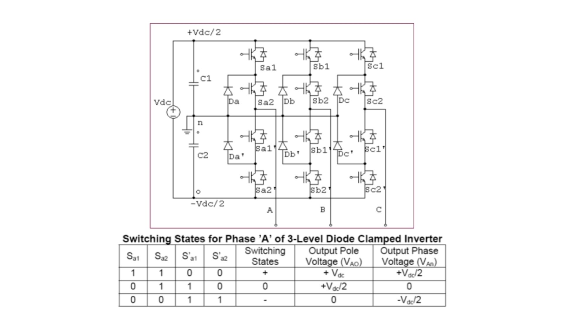
5-level diode clamped Multilevel Inverter Topology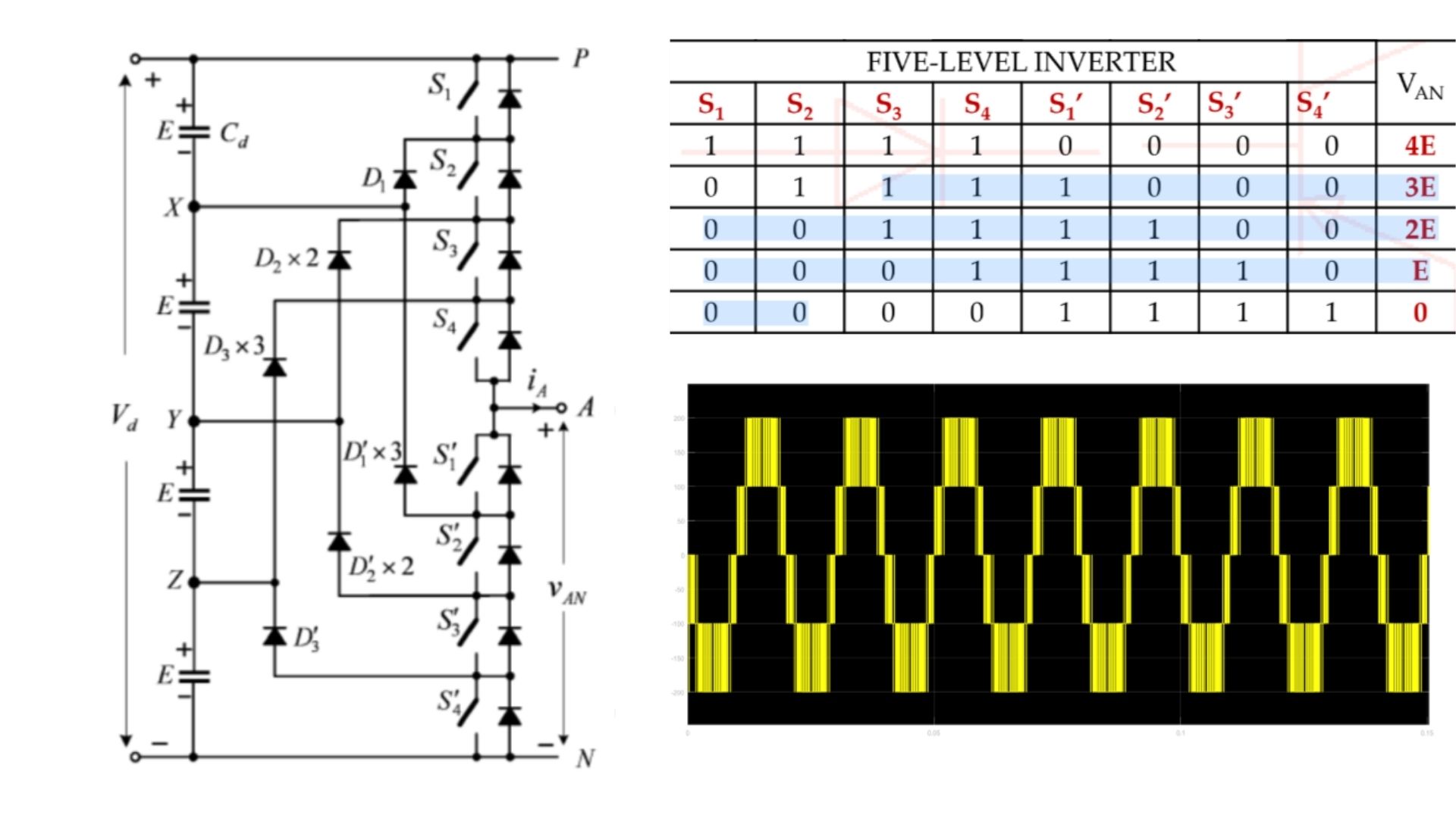
Advantages
- Switch voltage is half of the dc-link voltage.
- capacitance is low therefore they are precharged timely.
- Back-to-the-back inverters are used.
- High Efficiency at the fundamental frequency.
Disadvantages:
- The maximum output voltage is half of the dc input voltage.
- As the voltage level increases, the number of clamping diodes also increases, thus making the circuit more complex.
- If the control and monitoring are not precise, the voltage level will discharge.
Applications:
- Static var compensation
- Variable speed motor drives
- High voltage system interconnections
- High voltage DC and AC transmission lines
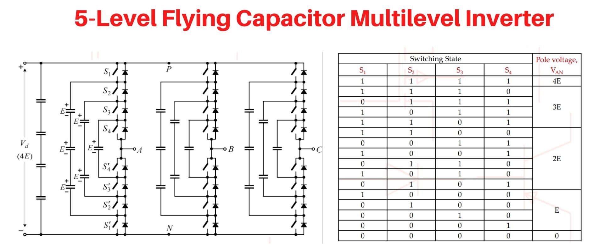
Flying Capacitors Multilevel Inverter (FCMLI)
Like diode clamped or Neutral Point Clamped MLI, flying capacitors MLI also use the same concept. The flying capacitor multilevel inverter (FCMLI) uses a ‘capacitor’ instead of the diode in order to limit the voltage so as to control the voltage stress in the electrical devices.
It is kind of an alternative to a diode clamped multilevel inverter topology. Here, Capacitors divide the input DC voltages and the voltage across each capacitor and the switch is Vdc. The output voltage is half of the dc input voltage.
FCMLI topology doesn’t require diode clamped. And the capacitor clamped are connected in series. The switching states are the same as that of the diode clamped inverter. It has switching redundancy within the phase for balancing the flying capacitor. The FCMLI can also able to control both active and reactive power flow. Lastly, flying capacitor topology has only switched and capacitor.
An m-level flying capacitor inverter needs:-
- Switches: (2m – 2)
- Number of capacitors: (m – 1)
3-Level Flying Capacitor Multilevel Inverter Topology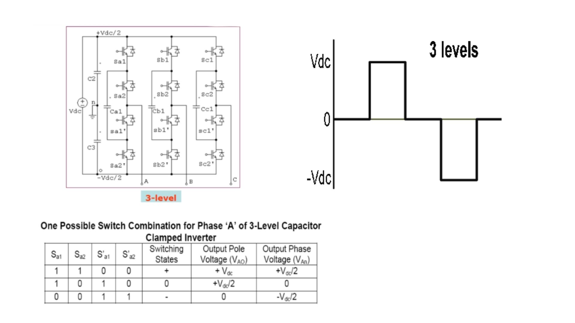
Applications:
- Induction motor control using DTC (Direct Torque Control) circuit
- Static var generation
- Both AC-DC and DC-AC conversion applications
- Converters with Harmonic distortion capability
- Sinusoidal current rectifiers
Advantages:
- Eliminates the clamping diode problems.
- Reduces dV/dt stress across the device.
- Additional switching states help to maintain charge balance in the capacitors.
Disadvantages:
- This inverter is Complex for a startup.
- Lower Switching efficiency.
- Capacitors are more expensive compared to diodes.
- Voltage control across all the capacitors is difficult.
Cascaded H-Bridge Multilevel Inverter (CHB-MLI)
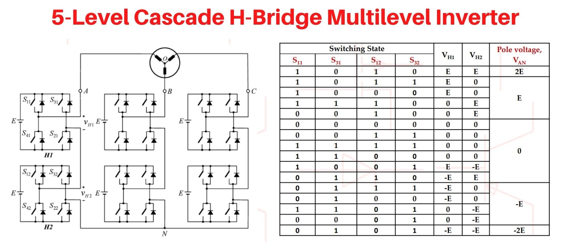
The cascaded H-bridge type of multilevel inverter is more popular than diode clamped and flying capacitors because it does not require any voltage balancing capacitors or clamping diodes. The output terminals of the H-bridge are connected in series with other output terminals of another H-bridge to produce an ac voltage via summation of the output H-bridges as shown in the figure below.
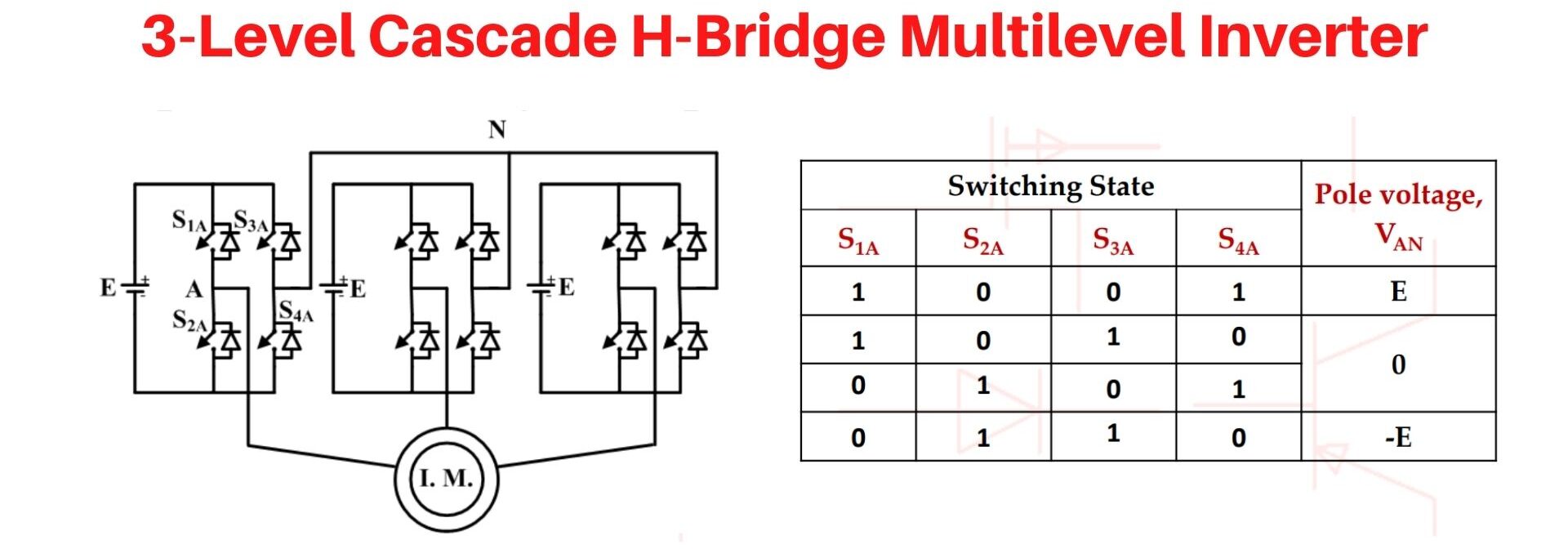
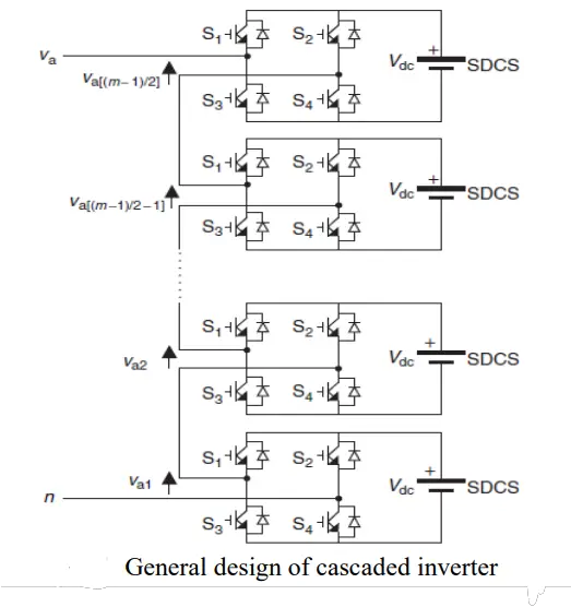 The structure of the H- bridge consists of four switches and a separated dc source. The inverter uses a series of connected H-bridge cells, each providing three different levels of DC voltages (zero, positive DC voltages, and negative DC voltages).
When s1 and s4 are turned on and s2 and s3 are turned off the positive voltage is obtained during the first half cycle. When s2 and s3 are turned on and s1 and s4 are turned off the negative voltage is obtained during the second half cycle. If (s1 and s2) or (s3 and s4) are turned off the zero voltage is generated.
Cascaded H-bridges inverter is such as common topology that is extensively manufactured by companies and used as useful power conversion. Most commonly, SPWM or MSPWM technique is applied on cascaded H-bridges converter switches to obtain synthesized voltage waveform. These techniques have higher switching frequency and lower harmonics.
If m cells are present, the number of output voltage levels will be 2m+1.
 Advantages:
- Easy packaging and storage
- Produce common-mode voltage, stress is reduced
- Low distortions in the input current
- Operates at both fundamental switching frequencies
- Total harmonic distortion is very low in the output waveform without any filter circuit
Disadvantages:
- Separate DC sources or capacitors are required for each module
- A More complex controller is required due to the number of capacitors
Applications:
- Motor drives
- Active filters
- Electric vehicle drives
- DC power source utilization
- Power factor compensators
- Back-to-back frequency link systems
- Interfacing with renewable energy resources.
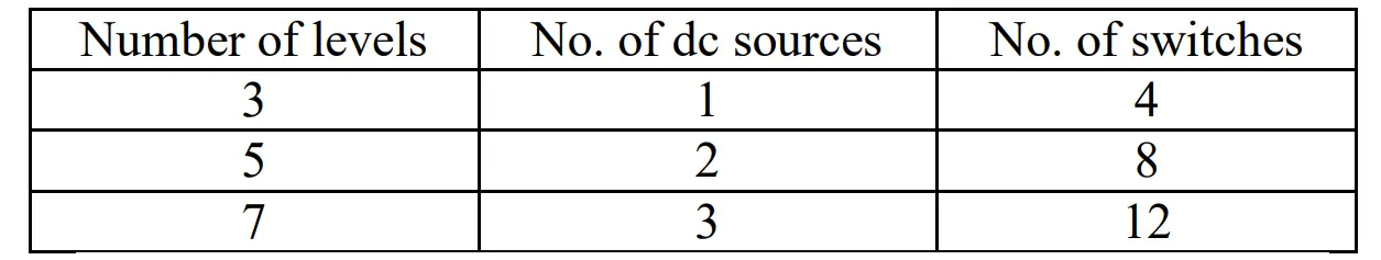
Comparison of the number of components used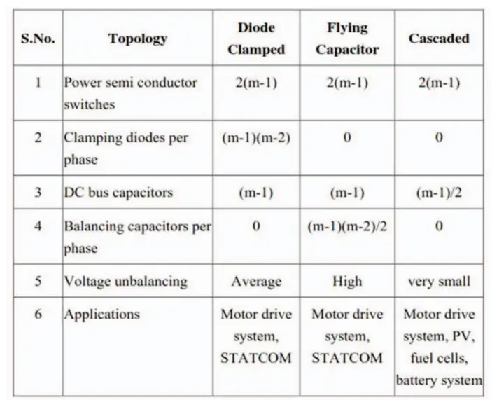
Modulation Techniques of Multi-Level Inverter
The multilevel inverter has different modulation techniques so as to obtain the require sinusoidal output. Modulation techniques are all about comparing the reference waveform with the carrier signal. The commonly used modulation topologies for multi-level inverters are as follows:
- Sinusoidal Pulse Width Modulation (SPWM).
- Selective Harmonic Eliminated Pulse Width Modulation (SHE-PWM).
- Phase-Shifted Sinusoidal Pulse Width Modulation (PS-SPWM)
- Alternative Phase Opposition Disposition Techniques (APOD)
- Phase Opposition Disposition Techniques (POD)
- Phase Disposition Techniques (PD)
Conclusion
The article presents a brief discussion on basic multi-level inverter topologies. Fundamental multilevel converter topology including its applications, advantages, and disadvantages of each technique have been discussed.
The main advantage of the MLI is that it finds a solution to the problems of total harmonics distortion, EMI, and dv/dt stress on a switch. Research works are in progress considering the structure complexity and control circuits. This helps to reduce the power of electronics components and improve the total harmonics profile and total cost of the system.
Hope you have learned many things from this piece of content. We are happy to provide you with more quality and the latest updates on the multilevel inverters and other electrical-related content. So, Keep learning with us always. Thanks!
")


")
 Current Feels Different to a Shock From Direct (DC) Current?")


