
You may have seen in your local area where different electrical tower configuration or design has been used. Is there any questions that come to your mind in that regard? If yes, then here in this article we are going to discuss the small topic of transmission lines.
When the power is being transmitted from the generation plant to the substation two configurations are usually used for transmission purposes namely single circuit and double circuit transmission lines.
In this article, we are going to discuss what actually is this configuration…
Single Circuit Transmission Line:
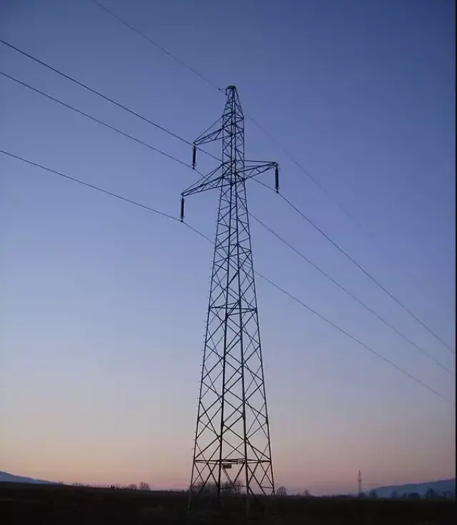
A single circuit or SC configuration has three conductors for the 3-Φ of the transmission (R, Y, B phase). To be more clear you can see the image from the above.
Double Circuit Transmission Line:
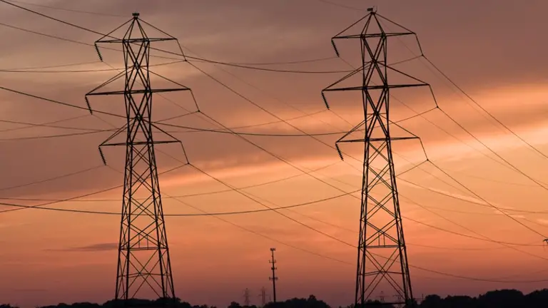 The Double circuit or DC configuration, it has six conductors. There are two 3-Φ lines comprising of total six conductors. A double Circuit is used when there is more power requirement in the area. It is reliable compared to SC configuration and can able to transmit bulk power over a distance.
A general thumb rule is that, if the number of conductors per bundle is 2 then it will be a 220 kV line while if the number of conductors per bundle is 4 then it will be a 400 kV line. This is a general thumb rule and variation is expected.
Using two circuits in one close path to each other will involve inductive coupling between the conductors. Therefore, proper protection schemes and equipment are needed to address and taken into account.
So, Lastly, as per the requirement, the electrical tower is installed in any area for transmission purposes.
Hope you find this article is informative…
 Current Feels Different to a Shock From Direct (DC) Current?")


")
 Current Feels Different to a Shock From Direct (DC) Current?")


Clearly explain