

In basic electrical, there are two important passive linear circuit elements: the capacitor and the inductor. Unlike resistors, which dissipate energy, capacitors and inductors do not dissipate but store energy, which can be retrieved at a later time. For this reason, capacitors and inductors are called storage elements.
The application of resistive circuits is quite limited. With the introduction of capacitors and inductors, we will be able to analyze more important and practical circuits.
In this article, we will discuss the concept and idea of a capacitor in a comprehensive manner. This piece of content will blow your concept of capacitor which you will need in practice and in various applications.
We begin by introducing capacitors and describing how to combine them in series or in parallel. Later, we do the same for inductors that you can read here.
In typical applications, we explore how capacitors are combined with op-amps to form integrators, differentiators, and analog computers.
Let’s dive in…
A Detail Study on Capacitors
A capacitor is a passive element designed to store energy in its electric field. Besides resistors, capacitors are the most common electrical components. Capacitors are used extensively in electronics, communications, computers, and power systems. For example, they are used in the tuning circuits of radio receivers and as dynamic memory elements in computer systems. A capacitor is typically constructed as depicted in the Figure below.
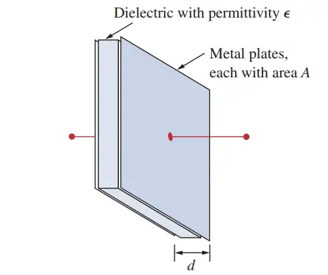
A capacitor consists of two conducting plates separated by an insulator(or dielectric).
In many practical applications, the plates may be aluminum foil while the dielectric may be air, ceramic, paper, or mica.
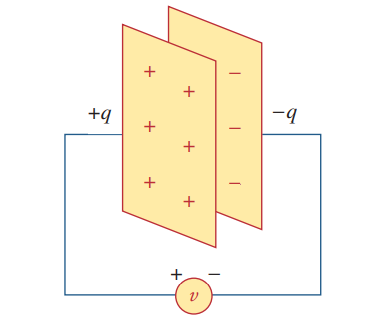
When a voltage source is connected to the capacitor, as in Fig. (2), the source deposits a positive charge ‘q’ on one plate and a negative charge ‘-q’ on the other. The capacitor is said to store the electric charge. The amount of charge stored, represented by q, is directly proportional to the applied voltage (v) so that,
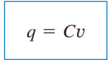
Where C, the constant of proportionality, is known as the capacitance of the capacitor. The unit of capacitance is the farad (F), in honor of the English physicist Michael Faraday (1791–1867). From Eq. given above, we may derive the following definition.
Capacitance is the ratio of the charge on one plate of a capacitor to the voltage difference between the two plates, measured in farads (F).
Alternatively, capacitance is the amount of charge stored per plate for a unit voltage difference in a capacitor.
Note: 1 farad = 1 coulomb/volt.
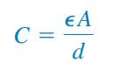
Although the capacitance ‘C’ of a capacitor is the ratio of the charge (q) per plate to the applied voltage (v) it does not depend on q or v It depends on the physical dimensions of the capacitor. For example, for the parallel-plate capacitor shown in Fig. (1), the capacitance is given by
where A is the surface area of each plate, d is the distance between the plates, and ‘∈’ is the permittivity of the dielectric material between the plates.
Factors Determine the Value of the Capacitance
Although Eq. (2) applies to only parallel-plate capacitors, we may infer from it that.
So in general, three factors determine the value of the capacitance:
- The surface area of the plates—the larger the area, the greater the capacitance.
- The spacing between the plates—the smaller the spacing, the greater the capacitance.
- The permittivity of the material—the higher the permittivity, the greater the capacitance.
Capacitors are commercially available in different values and types. Typically, capacitors have values in the picofarad (pF) to microfarad (μF))range. They are described by the dielectric material they are made of and by whether they are of fixed or variable type.
Circuit Symbols for Capacitors
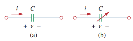
Figure (3) shows the circuit symbols for fixed and variable capacitors. Note that according to the passive sign convention, if v>0 and i>0 or if v<0 and i<0, the capacitor is being charged, and if v and i are less than 0, then the capacitor is discharging.
Common Types Of Capacitors
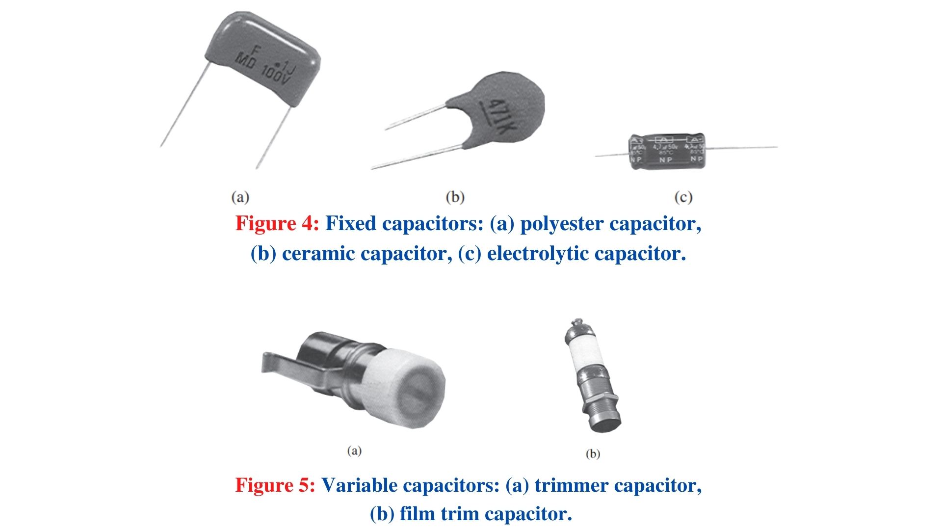
Figure (4) shows common types of fixed-value capacitors. Polyester capacitors are light in weight and stable, and their change with temperature is predictable. Instead of polyester, other dielectric materials such as mica and polystyrene may be used. Film capacitors are rolled and housed in metal or plastic films. Electrolytic capacitors produce very high capacitance.
Figure (5) shows the most common types of variable capacitors. The capacitance of a trimmer (or padder) capacitor is often placed in parallel with another capacitor so that the equivalent capacitance can be varied slightly. The capacitance of the variable air capacitor (meshed plates) is varied by turning the shaft. Variable capacitors are used in radio receivers allowing one to tune to various stations. In addition, capacitors are used to block dc, pass ac, shift phase, store energy, start motors, and suppress noise.
Current-Voltage Relationship of the Capacitor
To obtain the current-voltage relationship of the capacitor, we take the derivative of both sides of Eq. (1). Since,
Differentiating both sides of Eq. (1) gives,
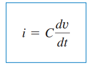
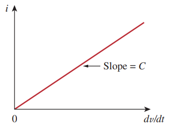
This is the current-voltage relationship for a capacitor, assuming the passive sign convention. The relationship is illustrated in Fig. 6 for a capacitor whose capacitance is independent of voltage. Capacitors that satisfy Eq. (4) are said to be linear. For a nonlinear capacitor, the plot of the current-voltage relationship is not a straight line. Although some capacitors are nonlinear, most are linear. We will assume linear capacitors in this book.
Voltage-Current Relation of the Capacitor
The voltage-current relation of the capacitor can be obtained by integrating both sides of Eq. (4). We get,
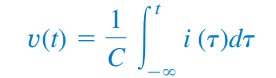
Or,
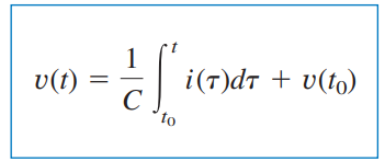
Where v(t0) = q(t0)/C is the voltage across the capacitor at time t0. Equation (6) shows that capacitor voltage depends on the past history of the capacitor current. Hence, the capacitor has memory—a property that is often exploited.
Power Delivered and Energy Stored
The instantaneous power delivered to the capacitor is-
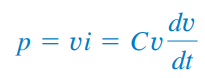
The energy stored in the capacitor is, therefore,
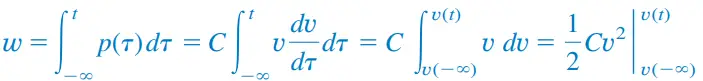
We note that because the capacitor was uncharged at t= -∞. Thus,
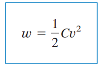
Using Eq. (1), we may rewrite Eq. (9) as
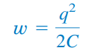
Equation (9) or (10) represents the energy stored in the electric field that exists between the plates of the capacitor. This energy can be retrieved since an ideal capacitor cannot dissipate energy. In fact, the word capacitor is derived from this element’s capacity to store energy in an electric field
Important Properties of a Capacitor
We should note the following important properties of a capacitor:
Properties 1: When the voltage across a capacitor is not changing with time (i.e., dc voltage), the current through the capacitor is zero. Thus,
A capacitor is an open circuit to dc.
However, if a battery (dc voltage) is connected across a capacitor, the capacitor charges.
Properties 2: The voltage on the capacitor must be continuous. Therefore,
The voltage on a capacitor cannot change abruptly.
The capacitor resists an abrupt change in the voltage across it.
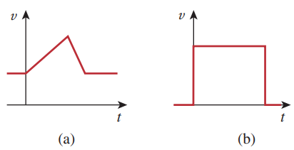
According to Eq. (4), a discontinuous change in voltage requires an infinite current, which is physically impossible. For example, the voltage across a capacitor may take the form shown in Fig. 7(a), whereas it is not physically possible for the capacitor voltage to take the form shown in Fig. 7(b) because of the abrupt changes. Conversely, the current through a capacitor can change instantaneously.
Out top Picks…!!
#1. 26 Most Asked Electrical Engineering Interview Questions and Answers [With PDF]
#2. What is an Electrical Fault? Definition, Types, Nature & Cause, its Effects, and statistics.
#3. DC Generator: Working Principle, Constructions, EMF Equation, and Types
Properties 3: The ideal capacitor does not dissipate energy. It takes power from the circuit when storing energy in its field and returns previously-stored energy when delivering power to the circuit.
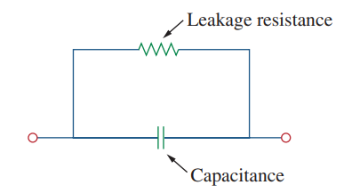
Properties 4: A real, nonideal capacitor has a parallel-model leakage resistance, as shown in Fig. 8. The leakage resistance may be as high as 100mΩ and can be neglected for most practical applications. For this reason, we will assume ideal capacitors in this book.
Series and Parallel Capacitors
- Parallel-connected Capacitor
We know from resistive circuits that a series-parallel combination is a powerful tool for reducing circuits. This technique can be extended to series-parallel connections of capacitors, which are sometimes encountered. We desire to replace these capacitors with a single equivalent capacitor Ceq.
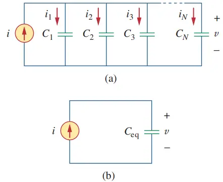
In order to obtain the equivalent capacitor Ceq of ‘N‘ capacitors in parallel, consider the circuit in Fig. 9(a). The equivalent circuit is in Fig. 9(b). Note that the capacitors have the same voltage across them. Applying KCL to Fig. 9(a),
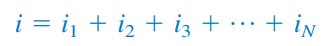
But ik= Ck dv/dt. Hence,
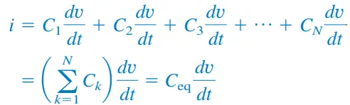
Where,
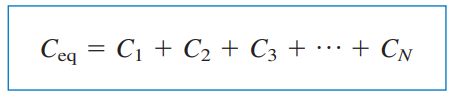
The equivalent capacitance of ‘N’ parallel-connected capacitors is the sum of the individual capacitances.
We observe that capacitors in parallel combine in the same manner as resistors in series.
- Series-connected Capacitor
We now obtain N capacitors connected in series by comparing the circuit in Fig. 10(a) with the equivalent circuit in Fig. 10(b). Note that the same current ‘I’ flows (and consequently the same charge) through the capacitors.
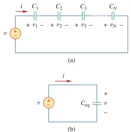
Now, Applying KVL to the loop in Fig. 10 (a),

But we know,
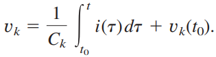
Therefore,
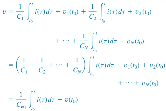
Where,
The initial voltage v(t0) across Ceq is required by KVL to be the sum of the capacitor voltages at t0. Or according to Eq. (13),
![]()
Thus, according to Eq. (13),
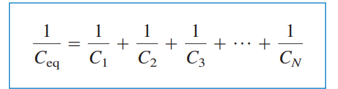
The equivalent capacitance of series-connected capacitors is the reciprocal of the sum of the reciprocals of the individual capacitances.
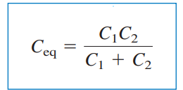
Note that capacitors in series combine in the same manner as resistors in parallel. For (i.e., two capacitors in series), Eq. (14) becomes:
![]()
Or,
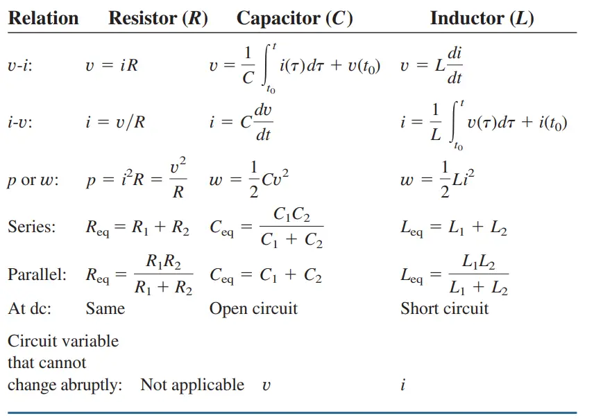
In conclusion, it is appropriate at this point to summarize the most important characteristics of the three basic circuit elements we have studied. The summary is given in the table below.
[Note: Passive sign convention is assumed.]
So that’s it..!
So, hope you have learned many things from this piece of content. So far we have discussed all these three important elements of basic electrical in detail that is: Resistor, Capacitor, and Inductor.
Promisingly, we are happy to provide you with more quality and the latest updates on electrical-related content. So, Keep learning with us always. Thanks!


")
 Current Feels Different to a Shock From Direct (DC) Current?")


