

In an electrical machine, there are two types of motors that work with Alternating Current (AC) i.e, Asynchronous Motor and Synchronous Motor.
The asynchronous motor is popularly known as the Induction motor. It is further divided into two types namely 1-phase induction motor and 3-phase induction motor. And, Synchronous motor also has two types i.e, Non-excited and DC Excited Motors (Discussed below).
In this piece, we will discuss only the synchronous motor.
What is a Synchronous Motor?
A Synchronous Motor is an AC electric motor in which the speed of the rotor is the same as that of the revolving field in the machine. The synchronous motor runs at synchronous speed (i.e, Ns= 120f/P). It is to be noted, that the synchronous motor is a 3-phase motor and its frequency remains constant due to which it obtain synchronized speed (constant speed).
However, it is not commonly used as it has different properties which doesn’t meet much demand.
Construction of Synchronous Motor
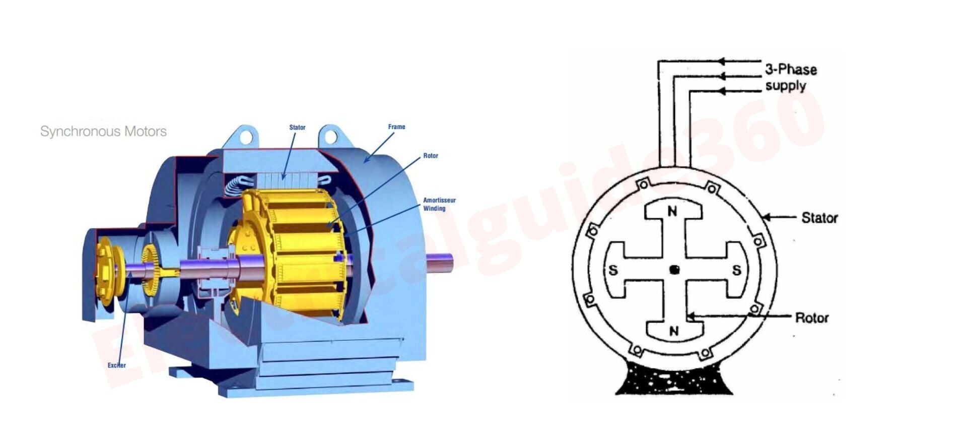
A synchronous motor is an electrical machine that runs at synchronous speed (constant speed) and converts electrical energy into mechanical energy. It is mainly an alternator being operated as a motor. There are main parts of a synchronous motor (like an alternator). These two parts are:-
(i) A Stator
A stator is a cylindrical core having a number of slots where 3-phase armature winding is adjusted into it. Every gap or surface of the core is insulated in order to prevent the flow of eddy current. The armature winding in the stator also receives power from a 3-phase supply.
(ii) A Rotor
The rotor is the rotating part of the synchronous machine, to be more simple it is a rod-like type. It is excited by the DC source. Rotor rotating speed is the same as the speed of the magnetic field. In synchronous motor, the rotor can be sub-classified into two parts: salient pole type and non-salient pole type. 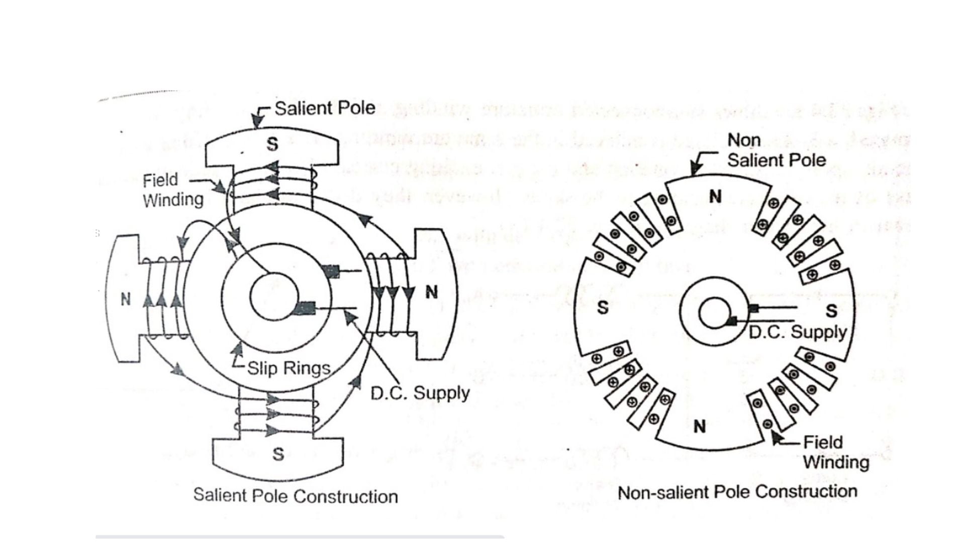 (a) Salient pole type rotor
Here the exciting coil is connected in series with two slip wings. Salient poles are excited by direct current in order to form alternative N pole and S poles. DC is fed into the windings. Direct current is supplied from the external exciter which is mounted on the rotor shaft. The stator is wound in such a way that there will be the same number of poles as the rotor pole.
The synchronous speed of a motor will depend on the number of poles:
Synchronous speed, Ns = 120f/P
Where,
- f = frequency of supply in Hz
- P= number of poles
Note that the synchronous motor is not self-starting and therefore it needs external means for starting it.
(b) Non-Salient pole type rotor
Non-salient pole rotors are a cylindrical shape that has parallel slots on them so that rotor windings can be placed. It uses solid steel for making this type of rotor.
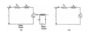
Equivalent Circuit Diagram
Working Principle of Synchronous Machine
A Synchronous motor has two main parts a stator and a rotor. The stationary part is the stator and the rotating part is the rotor.
Both the parts are “Doubly excited”. Double excited means there are two electrical inputs that are required to produce one mechanical output. In a simple way, there are two sets of input terminals to produce a mechanical output.
Let us now understand the operation principle of the 3-phase synchronous motor shown in the figure below:
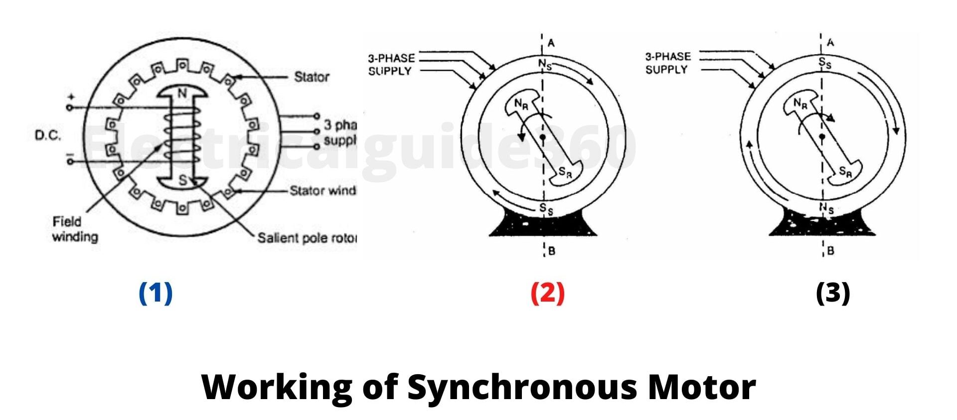
- The figure above, shows a 3-phase synchronous motor having two rotor poles namely NR and SR. Also the two poles namely NS and SS are wound for the stator. Now, direct voltage is applied to the rotor winding, and a 3-phase voltage is applied to the stator winding.
- After the supply is given, stator winding will produce a Rotating Magnetic Field that will revolve around the stator part at synchronous speed i.e, Ns (= 120 f/P). The direct (or zero frequency) current supplied in the rotor however will produce a Constant Magnetic Field. Thus, two situations occur at this moment, poles of the stator winding that revolves (i.e., NS – SS) and a pair of rotor poles that are stationary (i.e., NR – SR).
- Let us consider, a stator has given with 3-phase supply. Now, Stator will have a rotating magnetic field revolving around. Whereas, the rotor is at the stationary condition.
- In figure () When the stator pole is at positions A and B, the rotor will tend to move in an anticlockwise direction. This is because at this point the stator and rotor experience the same pole (i.e, NS and NR meet at a point) obtaining repulsive force and thus making the rotor move in an anticlockwise direction.
- After some time the poles at positions A and B will be reversed. Now, at this point, the rotor will tend to move in the same direction as that of the stator field (i.e, clockwise direction). This is because the stator and rotor will experience opposite poles thus obtaining attractive force and making the rotor move in the direction of the stator field.
- As a result, due to the high inertia of the rotor, the rotor is unable to move either clockwise or anti-clockwise direction due to repulsive force and attractive force. Hence, a synchronous motor is cannot start by itself because there is no self-starting torque produce in it.
How to make Synchronous Motor Self-Starting?
We know that synchronous motor cannot be started by itself. But it is possible to make synchronous motor self-starting by modifying its design. Now, to make synchronous motor self-starting, the squirrel-cage winding (also known as Damper Windig) is provided in the rotor part.
At starting the rotor field coils are not energized. when 3-Phase ac is supplied to the stator, the rotating magnetic field produced in the stator will get induced in the damper winding (squirrel cage) making the rotor starts moving just like an induction motor. This is because the speed of both rotor field and stator field will be different.
As the rotor reaches the synchronous speed, the rotor is excited with a direct current. At this point, the opposite polarity of both stator and rotor will have a magnetic attraction between them. The rotor poles and stator poles will be interlocked. Thus, making the speed of the rotor field equal to that of the stator field.
Now that the speed of the rotor is synchronized due to magnetic interlocking, there will be no flux cutting in the operation. So, there will be no current induced in the Damper winding. Hence, the operating of the squirrel cage is removed after all.
Note: It is important that excitation of the rotor with a direct current should be done at the right moment. That is why an arc is designed at the start in order to detect when the excitation should take place. Same polarity excitation may produce violent mechanical shock.
Types of Synchronous Motor
Depending on how the rotor is magnetized synchronous motor can be classified into two major types: Non-Excited Motors and DC Excited Motors.
1. Non-Excited Motors
In non-excited motors, the rotor is designed with high-retentivity steel such as cobalt steel. At synchronous speed, the rotor rotates due to the rotating magnetic field is almost constant. Perhaps, its magnetization needs to be done with the help of an external stator field.
The non-excited motors are made up of three different types, namely:
(a) Permanent magnet
(b) Reluctance, and
(c) Hysteresis designs
You can read Full details about their three types here.
2. DC Excited Motor
In DC Excited Motor, the supply is given to the stator winding from the external DC source. The field is produced in the stator winding and thus rotor excitation takes place. This type of motor is made of larger sizes which may be about more than one horsepower or one kilowatt.
Why is Synchronous Motor Lost out of Synchronism?
Synchronous Motor Lost out of Synchronism due to some of the following factors:
- Overload of Motor
- Low Supplied voltage
- Low Excitation Voltage
Applications
- Synchronous motors are used to improve the voltage regulation in the transmission lines.
- It is mainly used for low speed (< 300 r.p.m) the efficiency is high and can be adjusted to unity power factor.
- It is used for high-power electronics converters at very low frequencies which works at ultra-low speed. Some of the examples are drives crushers, variable-speed ball mills, and rotary kilns.
Advantages
- It has the ability to control the power factor.
- Irrespective of the load, the speed of the synchronous motor remains constant.
- In synchronous motor electromagnetic power varies linearly with the voltage.
- Synchronous motors can be used to improve power factors while carrying their rated load in the power plant.
Disadvantages
- Synchronous motors are not self-starting therefore require an external source for DC excitation.
- Its torque is zero. Therefore, cannot be started when there is a load.
- It cannot be used in an application where frequent starting is required.
- When the load is beyond its capability, the rotor and stator lost their synchronism and the motor abruptly stops.


")
")
 Current Feels Different to a Shock From Direct (DC) Current?")


