

As discussed earlier in Understanding Capacitor In Details, the basic electrical has two important passive linear circuit elements: the capacitor and the inductor. Unlike resistors, which dissipate energy, capacitors and inductors do not dissipate but store energy, which can be retrieved at a later time. For this reason, capacitors and inductors are called storage elements.
The application of resistive circuits is quite limited. With the introduction of capacitors and inductors, we will be able to analyze more important and practical circuits.
In this article, we will discuss the concept and idea of an inductor in a comprehensive manner. This piece of content will blow your concept of inductor which you will need in practice and in various applications.
let’s begin…
A Detail Study on Inductors
An inductor is a passive element designed to store energy in its magnetic field. Inductors find numerous applications in electronic and power systems. They are used in power supplies, transformers, radios, TVs, radars, and electric motors.
Any conductor of electric current has inductive properties and may be regarded as an inductor. But in order to enhance the inductive effect, a practical inductor is usually formed into a cylindrical coil with many turns of conducting wire, as shown in above Fig. (1).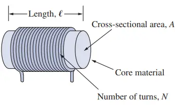
An inductor consists of a coil of conducting wire.
If the current is allowed to pass through an inductor, it is found that the voltage across the inductor is directly proportional to the time rate of change of the current. Using the passive sign convention,
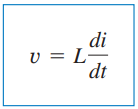
Where ‘L‘ is the constant of proportionality called the inductance of the inductor. The unit of inductance is the henry (H), named in honour of the American inventor Joseph Henry (1797–1878).
It is clear from above Eq. (1) that 1 henry equals 1 volt-second per ampere.
Inductance is the property whereby an inductor exhibits opposition to the change of current flowing through it, measured in henrys (H).
The inductance of an inductor depends on its physical dimension and construction. So, Formulas for calculating the inductance of inductors of different shapes are derived from electromagnetic theory depending on the construction and dimensions. It can be found in standard electrical engineering handbooks. For example, for the inductor (solenoid) shown in Fig. (1)-
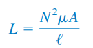
Where,
- L is the inductance of the inductor
- N is the number of turns
- l is the length
- A is the cross-sectional area, and
- μ is the permeability of the core
We can learn from Eq. (2) that inductance can be increased by:
- Increasing the number of turns of the coil
- Using a material with higher permeability as the core
- Increasing the cross-sectional area, or
- Reducing the length of the coil.
Like capacitors, commercially available inductors come in different values and types. Typical practical inductors have inductance values ranging from a few microhenrys (μH), as in communication systems, to tens of henrys (H) as in power systems.
Types of Inductor
The type of inductor can be classified depending core type used and depending on the mechanical construction. However, these are not only the way that the inductor can be classified.
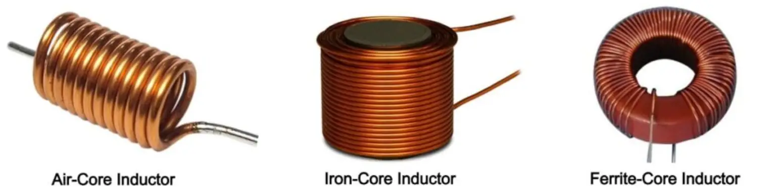
1. Depending on the core type used the inductor are classified into three types:
- Iron Core Inductor.
- Air Core Inductor.
- Ferrite Core
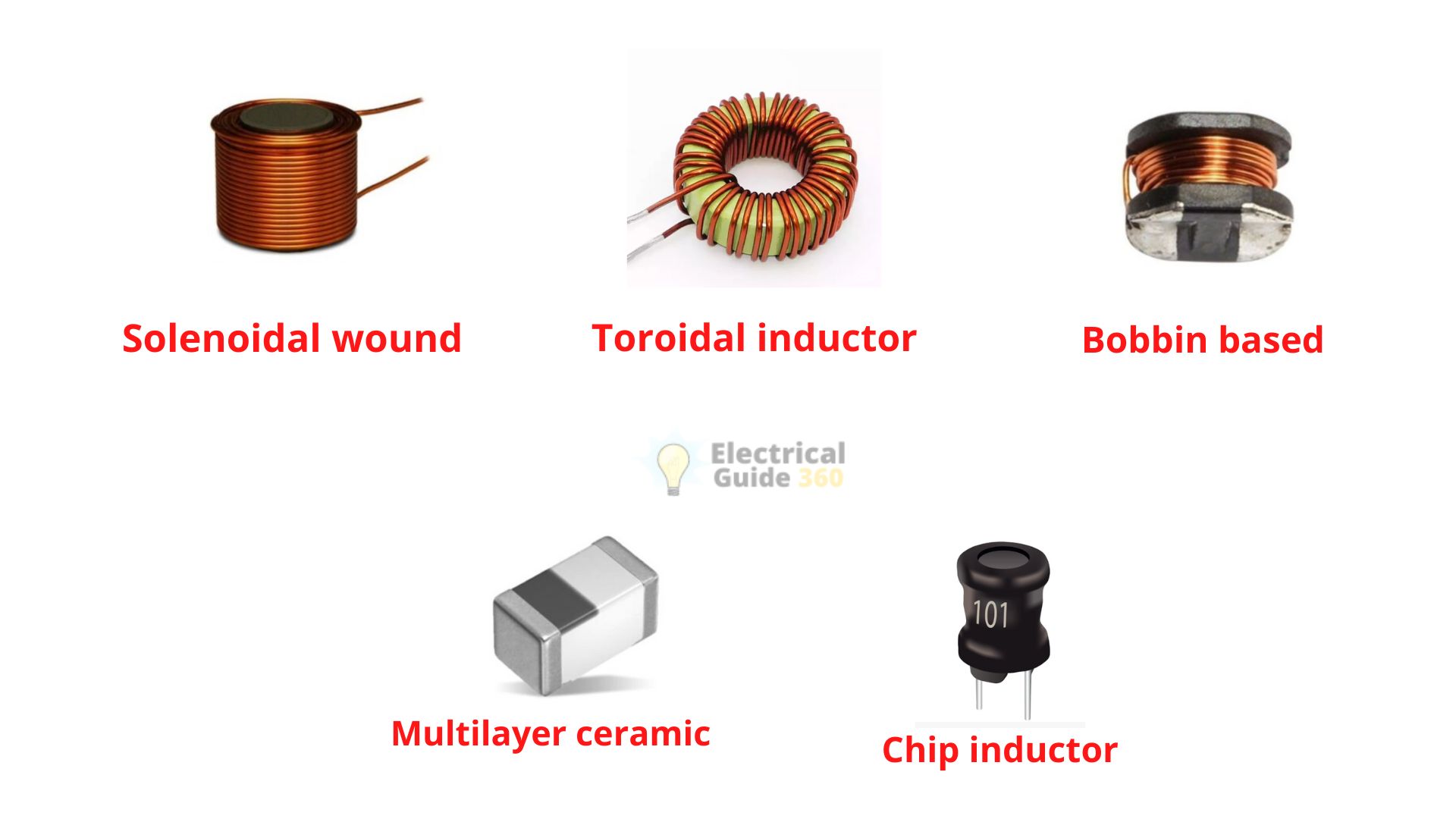
2. Depending on the mechanical construction the inductor are classified into five types:
- Solenoidal wound inductor
- Toroidal inductor
- Bobbin based inductor
- Multilayer ceramic inductor
- Chip inductor
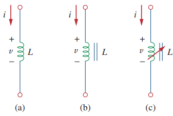
Circuit Symbols of Inductor
The circuit symbols for inductors are shown below following the passive sign convention.
Voltage-Current Relationship of an Inductor
Above equation (1) is the voltage-current relationship for an inductor. The figure below shows this relationship graphically for an inductor whose inductance is independent of the current. Such an inductor is known as a linear inductor. For a nonlinear inductor, the plot of Eq. (1) will not be a straight line because its inductance varies with the current.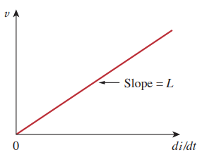
[Note: We will assume linear inductors in this textbook unless stated otherwise.]
Current-Voltage Relationship of an Inductor
The current-voltage relationship is obtained from Eq. (1) as
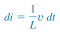
Integrating gives-
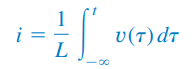
Or,
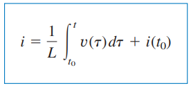
Where i(t0) is the total current for c< t < t0 and i (-∞) = 0. The idea of making i(-∞) = 0 is practical and reasonable because there must be a time in the past when there was no current in the inductor.
Power Delivered and Energy stored Equation
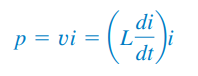
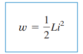
The inductor is designed to store energy in its magnetic field. The energy stored can be obtained from Eq. (1).
The power delivered to the inductor is;
The energy stored is
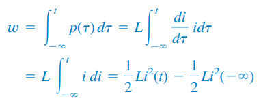
Since i(-∞) = 0,
Important Properties of an Inductor
We should note the following important properties of an inductor.
Properties 1: Note from Eq. (1) that the voltage across an inductor is zero when the current is constant. Thus,
An inductor acts like a short circuit to dc.
Properties 2: An important property of the inductor is its opposition to the change in current flowing through it.
The current through an inductor cannot change instantaneously.
According to Eq. (1), a discontinuous change in the current through an inductor requires an infinite voltage, which is not physically possible. Thus, an inductor opposes an abrupt change in the current through it.
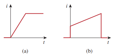
For example, the current through an inductor may take the form shown in Fig. (a), whereas the inductor current cannot take the form shown in Fig. (b) in real-life situations due to discontinuities. However, the voltage across an inductor can change abruptly.
Properties 3: Like the ideal capacitor, the ideal inductor does not dissipate energy. The energy stored in it can be retrieved at a later time. The inductor takes power from the circuit when storing energy and delivers power to the circuit when returning previously stored energy.
Properties 4: A practical, nonideal inductor has a significant resistive component, as shown below in Figure. This is due to the fact that the inductor is made of a conducting material such as copper, which has some resistance. This resistance is called the winding resistance (Rw) and it appears in series with the inductance of the inductor.
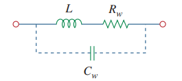
The presence of Rw makes it both an energy storage device and an energy dissipation device. Since Rw is usually very small, it is ignored in most cases.
The nonideal inductor also has a winding capacitance (Cw) due to the capacitive coupling between the conducting coils. Cw is very small and can be ignored in most cases, except at high frequencies. We will assume ideal inductors in this book.
Series and Parallel Inductors
Now that we have learned about the passive elements inductor, it is necessary to extend the powerful tool of series-parallel combination. Like capacitor series and parallel connection, we need to know how to find the equivalent inductance of a series-connected or parallel-connected set of inductors found in practical circuits.
- Series-Connected Inductor
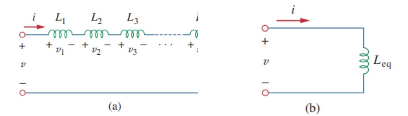
Consider a series connection of N inductors, as shown in above Fig. 1(a), with the equivalent circuit shown in Fig. 2(b). The inductors have the same current through them. Applying KVL to the loop,
Substituting vk = Lk di/dt results in
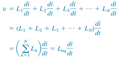
Where
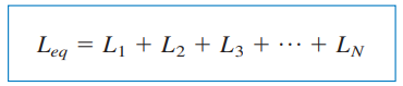
Thus,
The equivalent inductance of series-connected inductors is the sum of the individual inductances.
Inductors in series are combined in exactly the same way as resistors in series.
- Parallel Connection of Inductors
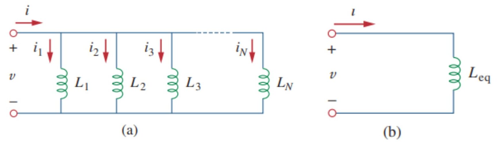
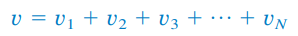
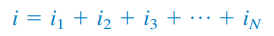
We now consider a parallel connection of N inductors, as shown in Fig. 6.30(a), with the equivalent circuit in Fig. 6.30(b). The inductors have the same voltage across them. Using KCL,
But,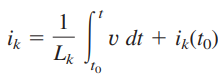
Hence,
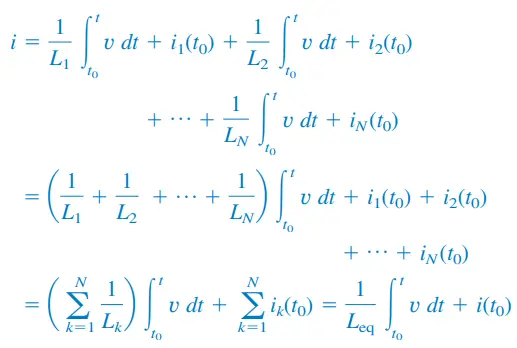
Where,
The initial current through Leq at t = t0 is expected by KCL to be the sum of the inductor currents at t0. Thus, according to Eq. (13),
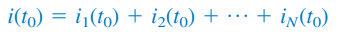
According to Eq. (14),
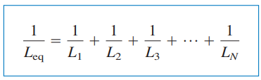
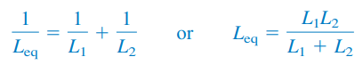
The equivalent inductance of parallel inductors is the reciprocal of the sum of the reciprocals of the individual inductances.
[Note that the inductors in parallel are combined in the same way as resistors in parallel.]
For two inductors in parallel, Eq. (14) becomes-
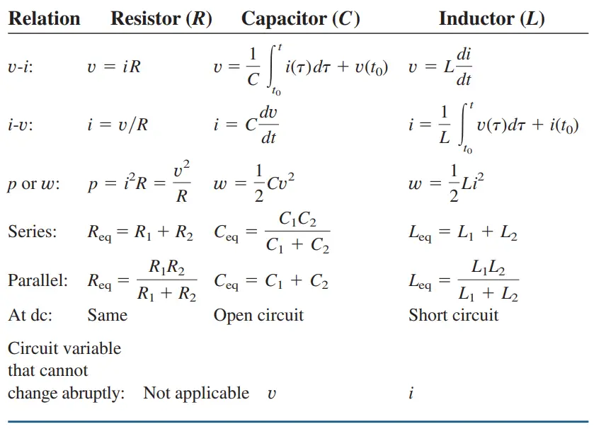
In conclusion, it is appropriate at this point to summarize the most important characteristics of the three basic circuit elements we have studied. The summary is given in the table below.
[Note: Passive sign convention is assumed.]
So, hope you have learned many things from this piece of content. So far we have discussed all these three important elements of basic electrical in detail that is: Resistor, Capacitor, and Inductor.
Promisingly, we are happy to provide you with more quality and the latest updates on electrical-related content. So, Keep learning with us always. Thanks!


")
 Current Feels Different to a Shock From Direct (DC) Current?")


